Project objects with different compositional and plastic structures should be depicted in the most advantageous for each of them graphic technique. In some cases, axonometric drawings are preferred for this purpose. Axonometric drawing - conditional image of the object in axonometric, the very concept of which originated from the phrase "axon" (axis) and "metreo" (measured) - terms taken from the ancient Greek language. The method of axonometric projection is a perspective image of the object, parallelly projected onto the visual plane at a certain angle to it (Fig. 6). Axonometric drawing - a tool that allows you to get when looking at an object in perspective from the top or bottom points of view, the most complete impression of its three-dimensional and spatial characteristics.
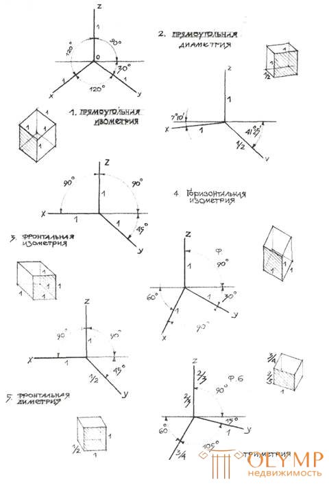
Types of axonometric images. In our country, types of axonometric projections are classified and subject to state standards. Please note that the images in fig. 6 axonometric drawings are oriented along three axes, among which the vertical axis is denoted z , the left axis from the vertical is denoted x , the right axis from the vertical is denoted y . Along axes of axonometric figures there is a numerical designation of proportional reduction (distortion) of the faces of the depicted figures, referred to in the text as “distortion index”: 1 - the axis or face of the figure with this index is not reduced, has linear proportions 1: 1; 3/4 - axis or edge of the figure with such an index is reduced in proportions 3: 4; 2/3 - an axis or a face of a figure with such an index is reduced in proportions 2: 3; 1/2 - in the direction of the given axis or face of the figure the image is reduced in proportions 1: 2.

Fig. 6. Axonometric construction schemes according to GOST.
In real or educational design according to GOST 2.317–69 axonometric projections are divided into rectangular and oblique axonometric projections.
Rectangular, where the projecting rays are perpendicular to the picture plane. Rectangular projections are divided into:
- a rectangular isometric projection, where the angles between the z , x , y axes are 120 °, and the angles between the horizontal line and the x and y axes are 30 °, where the image along all three axes is not reduced and is indicated by the reduction index 1 (Fig. 6, 1) ;
- rectangular dimetric projection, where the x axis is directed to the horizontal line at an angle of 7 ° 10 ', the y axis is directed to the horizontal line at an angle of 41 ° 25'. The index of contraction of the image along the z axis, and x is 1, and the index of contraction along the y axis is 1/2 (Fig. 6, 2 );
Oblique projections where the projecting rays are inclined to the picture plane. Oblique projections in turn are divided into:
- frontal isometric projection, where the angle between the z and x axes is 90 °, and the angle of the y axis to the horizontal line is 45 °. The reduction indices on all three axes z , x , y is 1 (Fig. 6, 3) ;
- horizontal isometric projection, where the angle at which the x- axis meets the horizontal line is 60 °, and the angle of the y- axis to the horizontal straight line is 30 °. The reduction index on all three axes z , x , y is 1 (fig. 6, 4 );
- frontal dimetric projection, where the angle between the z and x axes is 90 °, and the y axis meets the horizontal line at an angle of 45 °. The distortion index in the z and x axes is 1, and the Y distortion index is 1/2 (Fig. 6, 5) ;
- The trimetric projection is distinguished by different indices of the distortion index along all three axes. With the horizontal straight line, the x axis is at an angle of 60 °, the y axis is at an angle of 15 °, and the angle between the x and y axes is 105 °. Quantitative indicators of the distortion index on the three axes within certain limits may vary. In fig. 6, 6 , the z- axis distortion indicators are 2/3, the x axis is 3/4, and the y axis is 1.
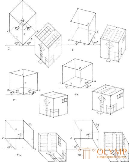
Figures 7, 8, 9, 10, 11, 12 in fig. 7 demonstrate axonometric techniques widely used in the United States. The presented techniques differ significantly from axonometric images according to the Russian GOST and are of particular interest to the perspective images of the designed objects.
When performing all types of axonometric drawings should not:
- use axonometric drawings without a strict orientation of the drawing projections relative to the vertical and horizontal axes of the drawing picture plane;

Fig. 7. Building nontraditional axonometric schemes
- faces of axonometric projections should be drawn, strictly observing the parallelism of straight lines;
- one should not arbitrarily select the proportions of distortion along the three axes of axonometry, proportional to the distortion of the faces of the axonometric image should be extremely accurate;
- when depicting objects with plans cylindrical or close to a square, do not use the axonometric techniques shown in Fig. 6. ( 1, 3 ) .
Что бы оставить комментарий войдите
Комментарии (0)