4.1. The concept of tracing linear structures
Linear structures are called, which have a large length with a relatively small width. Such structures include railways, highways, canals, pipelines, etc.
The longitudinal axis of the linear structure is called a highway .
T rassa railway - the longitudinal axis of the road at the level of the edge of the subgrade.

Fig. 1. The route of the railway.
The main elements of the route: the plan and the longitudinal profile .
In terms of the route consists of straight sections connected by curves of constant or variable radius of curvature.
In the longitudinal profile, the route consists of straight sections of different slopes, connected by vertical curves.
The complex of works on determining the position of a track in space is called tracing .
The main requirement for road routes is to ensure the smoothness and safety of traffic at a given speed. Therefore, the route plan and its profile must meet certain requirements that are recommended by the design specifications, where the maximum allowable (guiding) slopes, the minimum possible radii of curves, and other elements are specified.
At the same time, the route must pass in such a way as to ensure minimum expenses for the construction of the road.
Initially, the office tracing is performed - drawing the route on topographic maps, plans or aerial photography materials. At the same time it is necessary to bypass the contour and relief obstacles. In these cases, there are options for laying the route.
In flat terrain with less than permissible slopes, free design is performed using a free move , in which the route is laid in the shortest direction, and its position depends only on natural and artificial obstacles.
In hilly and mountainous areas, the slope of the slopes exceeds the allowable slopes of the road, and in such conditions, the route is laid tense move , i.e. looking for its directions that have a maximum allowable slope. As a result, a winding road is obtained, which is straightened in some areas, replacing the broken line with a straight line. In the highlands, to ensure acceptable slope, the route is laid in the form of serpentines and loops.
After cameral tracing, field surveys are performed, during which the final position of the track is established. The project of the track is carried out to the terrain. Lay the track in the form of a theodolite-leveling or theodolite-high-altitude course.
Then proceed to the working design. For each structure they create a project, and for the track they lay a theodolite-leveling course.
4.2. Laying tracks on the ground
In terms of the axis of the route is laid in the form of a traverse.
Points that are vertices of angles serve as a planning justification. The top of the corner is fixed with a stake that is driven flush with the ground. At a distance of 1 meter from the stake, on the outside of the angle on its bisector, a column with a curtain is installed (Fig. 2). On the gauge facing the top of the corner, an inscription is made indicating the number of the top of the corner, the year of work, the angle of rotation of the road, the radius of the curve inscribed in the corner, the distance from the beginning of the road. From the top of the corner, they measure the distance to located near local objects (a tree, a corner of a building, a crossroads, a boulder, etc.) and show them on the outline - a scheme drawn up to facilitate the search for the top of the corner.

Fig. 2. Fixing corners on the road
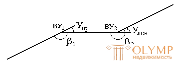
A theodolite is set above the stake that fixes the top of the corner and measured in one reception with an accuracy of 0.5 'the angle between the directions to adjacent vertices of the angles lying to the right along the route (Fig. 3).

Fig. 3. Turning angles and right angles along the course
After measurement, calculate the angle of rotation of the route.
The angle of rotation of the route is the angle between the continued previous and subsequent directions. It is calculated by the formulas

Then perform a breakdown of the curved sections of the route.
4.3. Control of angular measurements on the track
Let the direction angle of the initial direction of the path α0 be given. The angles of rotation of the route U1, U2, U3, U4, ..., Un are measured by a theodolite (Fig. 4).

Fig. 4. Determination of the directional angles of the angles of rotation of the route
Find the directional angles of the rest directions of the route directly from fig. 79
α1 = α0 + U1,
α 2 = α 1 - U2,
α 3 = α 2 + U3,
α 4 = α 3 - V4,
...
α n = α n-1 - Un,
that is, the directional angle of the subsequent direction is equal to the directional angle of the previous direction plus the right angle of rotation or minus the left angle of rotation:

adding all equalities, we get:

This formula is used to control the calculation of the directional angles of the sides of the track.
Control of the angular measurements on the track is performed by calculating the value of the practical angular discrepancy of the stroke  measured angles of rotation U1, U2, U3, U4, ..., Un and directional angles α0 of the initial and αn of the final directions of the route (Fig. 4)

If a  does not exceed the allowable discrepancy (for traverse moves -
  ), determine the amendments that are counted with the opposite sign when correcting the measured angles. After that, the directional angles of the rest directions of the route are determined.
4.4. Breakdown of stationing, widths, filming a strip of terrain
The distances on the track are measured twice. First, together with the angular measurements using distance meters or measuring tapes determine the distance between the vertices of the corners. At angles of inclination greater than 2 °, the measured distances are reduced by the amount of correction for the inclination.
The second time distance is measured for picket layout, curve elements and transverse profiles . These measurements are performed usually with measuring tapes or 50-meter tape measures.
Depending on the terrain conditions, the limiting relative error of linear measurements is allowed 1: 1000 - 1: 2000.
During the breakdown of picket, they simultaneously survey the situation points located near the highway.
The picket is called the end points that denote parts of a certain length. For railways and roads picket is considered a segment of 100 meters. The picket is denoted by the letters “PC” and a number, for example, “PK12” (Fig. 5) indicates that this point is located 1200 m from the beginning of the route.

Fig. 5. Breakdown of picket
Pickets are fixed on the ground, hammering level with the ground count. Next to it (in front of it along the route, at a distance of 20–25 cm) a second count of gatehouses , towering above the ground, is clogged . At the gatehouse sign the ordinal number of the picket, for example PC12.
In addition to pickets on the ground, positive points are also noted: relief - characteristic excesses of the terrain (with an accuracy of 1 m) and contour - structures crossed by the route, waterways, land borders, roads (with an accuracy of 1 cm). Plus points are also fixed with a peg and a gatehouse. On the gatehouse they write the number of the picket and the distance from it in meters. For example, PK13 + 32, which means 32 meters after PK13 or 1332 meters from the start of the course.
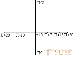
Where the terrain has a noticeable (more than 1: 5) cross slope, perpendiculars to the road, called diameters , are broken at each station and plus point. They are divided to both sides of the route with a length of 15–30 m in such a way as to ensure the filming of the entire strip of terrain. The end points of the widths are fixed with a point and a gatehouse, plus points located in places where the terrain changes - only with gatehouses. They write the distance from the axis of the route: with the letter "P", if to the right of the axis, "L" - to the left (Fig. 6).

Fig. 6. Breakdown of the diameter.
Simultaneously with the breakdown of picket on both sides of the axis of the route, they are shooting a strip of terrain. The width of the shooting strip depends on the nature of the future structure and is set by the relevant technical instructions.
In a strip 20–25 m wide on each side of the axis of the route, the survey is performed instrumentally, mainly by the method of perpendiculars, and further - by eye.
4.5. Picket magazine
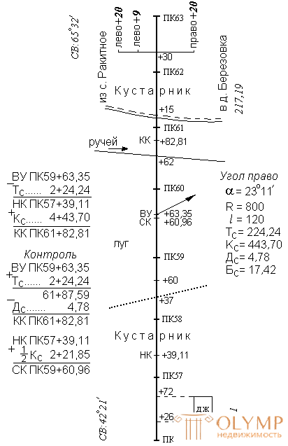
At the breakdown of the route, a picket log is kept (Fig. 7), made of millimeter paper measuring 10 × 15 cm. It is the main field document when building its plan and situation on the longitudinal profile of the route.
In the middle of the page of the pickup journal, a straight line is drawn depicting the axis of the route, on it at a scale of 1: 2000 strokes mark the position of the pickets and plus points, signing their values next to them. Each new page begins with a picket, with which the previous one is completed. In the places where the road turns from the axis, the direction of rotation is indicated by an arrow and the value of the angle of rotation and the elements of the curve are recorded in a column near the free space. On the axis of the route mark the main points of the curves (beginning, middle and end), sign their station. Opposite to straight sections of the route, write their points and lengths. The situation in the magazine sketched schematically, indicating the distance from the axis of the route to the objects and the dimensions of buildings.

Fig. 7. Picket magazine.
4.6. Questions for self-control
1. What kind of work does tracing include?
2. What is the track plan?
3. What is the longitudinal profile of the track?
4. What is the turn angle of the track and how is it determined?
5. How to break the pickup, plus points and widths?
6. How do the directional angles of the sides of the track in the angles of rotation?
7. What is a pickup magazine and what is its content?
Что бы оставить комментарий войдите
Комментарии (0)