Geodetic measurements are reduced to the determination of the relative position of points on the earth's surface. In order to weaken the effect of measurement errors and prevent their accumulation during geodetic surveying of terrain sections, it is customary to conduct work from the general to the particular . To do this, from the set of determined points of the earth’s surface area, the most characteristic ones are distinguished and their position is determined first of all. Such points are called pivot points. These points form a geodetic support network (geodetic base), i.e. form a general outline, on the basis of which further shooting is carried out with the necessary, although lower accuracy.
In order for the survey results to be reliable, all the most important geodetic operations must be carried out with the control. Therefore, the principle of a single step forward without control of previous actions underlies the quality of geodetic works.
8.2. Purpose and types of state geodetic networks
Since 1919, in our country, the beginning of a scientifically based organization of all topographic and geodetic works. Executive, control, permissive and supervisory functions in their production were combined in the Higher Geodesic Administration (VSU). Subsequently, it was transformed into the General Directorate of Geodesy and Cartography. From March 1, 2009, these functions were transferred to the Federal Service for State Registration, Cadastre and Cartography.
One of the most important tasks of this state body is the creation of a state geodetic network (GHS) on the territory of our country.
The state geodetic network is a set of reference geodetic points, firmly fixed on the ground, the relative position of which is precisely defined in a single state system of coordinates and heights.
Geodetic networks are divided into a state geodetic network, a geodetic network of thickening and a survey geodetic network.
The state geodetic network is the starting point for other geodetic networks. It is divided into planned and high-altitude .
The planned state geodetic network is created by astronomical or geodetic methods.
With the astronomical method, the planned position of each of the individual network points is determined independently of each other from astronomical observations.
The geodesic method consists in the fact that to determine the coordinates of points, from astronomical observations, the coordinates of only a few points, called the origin, are found. Further definition of the planned position of the points produced by geodetic measurements on the ground.
High-altitude state geodetic network is created by the method of geometric leveling.
8.3. Planned state geodetic networks. Methods of their creation
The main methods of creating a state geodetic network are triangulation, trilateration, polygonometry and satellite coordinate definitions.
Triangulation (Fig. 68, a) is a chain of adjacent triangles, each of which measures all angles with high-precision theodolites. In addition, I measure the length of the sides at the beginning and end of the chain.
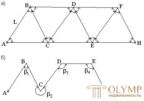
Fig. 68. The scheme of triangulation (a) and polygonometry (b).
In the network of triangulation, the basis L and the coordinates of points A and B are known. To determine the coordinates of the other points of the network, the horizontal angles are measured in triangles.
Triangulation is divided into classes 1, 2, 3, 4. Triangles of different classes differ in lengths of sides and accuracy of measuring angles and bases.
The development of networks of triangulation is performed in compliance with the basic principle “from the general to the particular”, i.e. first, class 1 triangulation is built, and then in series 2, 3, and 4.
The points of the state geodetic network are fixed on the ground by the centers. To ensure mutual visibility between the points above the centers, geodetic signs are made of wood or metal. They have a device for installing the instrument, a platform for the observer and a sight device.
Depending on the design, land-based geodetic signs are divided into pyramids and simple and complex signals.
Types of underground centers are established depending on the physiographic conditions of the region, the composition of the soil and the depth of seasonal soil freezing. For example, the center of a state geodetic network of 1-4 classes of type 1 according to the instructions “Centers and Reper of the state geodetic network” (Moscow, Nedra, 1973) is intended for the southern zone of seasonal freezing of soils. It consists of a reinforced concrete pylon with a section of 16x16 cm (or asbestos-cement pipe 14-16 cm filled with concrete) and a concrete anchor. The pylon is cemented into an anchor. The base of the center should be located below the depth of seasonal freezing of the soil at least 0.5 m and at least 1.3 m from the ground surface. At the top of the mark, a cast iron mark is concreted on the ground level. Above the mark, within a radius of 0.5 m, the soil is poured with a layer of 10-15 cm. An identification pole with a guard plate is installed 1.5 m from the center.
Nowadays radio equipment is widely used to determine distances between network points with relative errors of 1: 100,000 - 1: 1,000,000. This makes it possible to build geodetic networks using the trilateration method, where only the sides measurement is performed in triangle networks. The magnitude of the angles is calculated by the trigonometric method.
The method of polygonometry (Fig. 68, b) consists in the fact that the geodetic reference points are connected with each other by turns, called polygonometric ones. They measure the distance and lying to the right angles.
Satellite methods for creating geodetic networks are divided into geometric and dynamic. In the geometric method, an artificial satellite of the Earth is used as a high sighting target, in a dynamic method, the satellite is a carrier of coordinates.
8.4. High-altitude state geodetic networks
The state high-altitude geodetic network is a leveling network of classes I, II, III and IV. At the same time, the networks of classes I and II are the high-altitude base, with the help of which a unified system of heights is established throughout the country.
On the lines I, II, III and IV classes lay secular, fundamental, soil, rock, wall and temporary benchmarks.
The age-old and fundamental benchmarks are laid in the rocks or in the ground. They are characterized by increased stability and ensure the safety of high-altitude basis for a long time. Centuries-old benchmarks fix the crossings of the leveling lines of class I, and the fundamental ones lay on the lines of classes I and II no less than 60 km away.
Temporary frames are used as a high-altitude base for topographic surveys, and also include grade II, III and IV grading lines.
8.5. Surveying Networks
Survey networks are a geodetic basis for solving engineering and geodetic tasks. They are created as a filming rationale for the production of topographic surveys, removal of engineering structures to the area, as well as for the planned and high-altitude binding of individual objects.
The filming justification is broken down from the points of the planned and high-altitude support networks.
The most common type of survey is theodolite moves (fig. 69), based on one or two starting points. They represent geodesic constructions in the form of broken lines, in which the angles are measured by one complete reception with the help of a technical theodolite, and the sides - with steel 20-meter tape or rangefinders, providing a given accuracy. Theodolite passages can be closed or open.

Fig. 69. Theodolite passages: closed (a); open (b).
The lengths of the lines (sides) of theodolite passages depend on the scale of the survey and the conditions of the area to be removed and should be no more than 350 m and no less than 20 m.
The angles of rotation at the points of travel are measured with a theodolite with a mean square error of 0.5 ′ in a single step. The discrepancy between the values of the angles in the semi-receptions no more than double theodolite accuracy.
The points of the shooting justification, as a rule, are fixed on the ground with temporary signs: wooden stakes, poles, metal pins, pipes.
If these points are supposed to be used in the future for other purposes, they are fixed with permanent signs.
8.6. Planned binding peaks of theodolite course to points GHS
The set of geodetic measurements and calculations necessary to determine the position of the nodes of the traverse in the state coordinate system is called anchoring.
Binding can be done by several methods.
1. Planned binding by the method of angular serifs (Fig. 70).
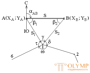
Fig. 70. Binding theodolite course by the method of angular serif.
Given: A  ; AT
; AT  .
.
Measured angles: 
Measurement control:  ;
; 
Find the coordinates of point 1  ; directional angle
  .
.
1. The solution of the inverse geodetic problem


Control : 
2. Solving a triangle binding
 ;
; 
3. Transfer of directional angles


Computation Control: 
4. Solution of the direct geodetic problem
 |
 |
 |
 |
 |
 |
 |
 |
If the discrepancy in the coordinates is not more than 0.02 m, then find the average values of the coordinates X1 and Y1.
2. The method of carrying the coordinates (Fig. 71).
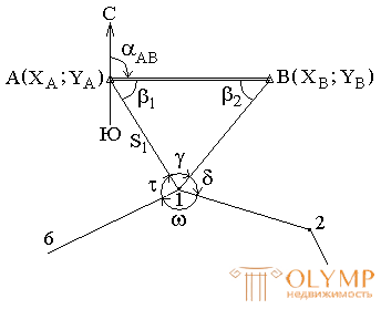
Fig. 71. Binding by the method of carrying coordinates
Given: A (XA; YA); B (XB; YB).
Measured: 
Control: 
Find the coordinates of point 1 (X1; Y1); directional angle (1 - 2).
1. The solution of the inverse geodetic problem.
2. Solving a triangle binding


3. Transfer of directional angles.
4. Solving the direct geodesic task.
3. The method of binding a traverse to a single reference point with a known direction in it (Fig. 72) ..
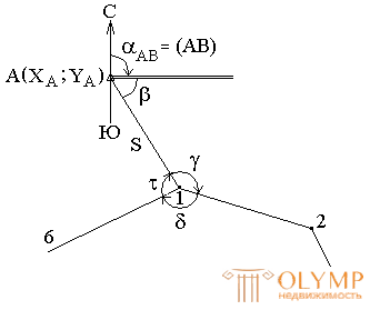
Fig. 72. Binding to one point with a known direction.
Given: A (XA; YA); 
Measured: S; angles: 
Control: 
Find the coordinates of point 1 (X1; Y1); directional angle (1 - 2).
1. Transfer of directional angles


2. Solution of a direct geodetic task.


To control the binding, you need to attach another vertex of the traverse to the reference point.
8.7. Questions for self-control
1. What are the basic principles of building geodetic networks?
2. What is the essence of the method of triangulation?
3. What is the essence of the trilateration method?
4. What is the essence of the method of polygonometry?
5. How are angles and lines measured when creating a traverse?
6. What is the task of the planned binding of the traverse to the support points?
7. What is the essence of direct and inverse geodetic tasks?
Что бы оставить комментарий войдите
Комментарии (0)