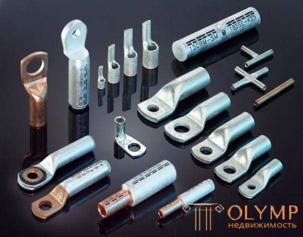
Previously, the most affordable way to connect the wires was twisting. Twist used everywhere. And regardless of what were aluminum wires or copper. Although, to tell the truth, copper was used in few places. But progress, as they say, does not stand still and today many ways to connect wires are already known.
I will not enumerate everything, I will mention only the most popular ones, this is of course: connecting with the help of terminal blocks (Wago), welding, soldering, crimping. Each of these methods has its pros and cons, and also requires a certain amount of effort and effort.
So for welding you need a welding machine, not all of them know how to use. Especially for the power supply of the welding machine, electricity is needed, and this is not entirely convenient when working in a de-energized area. Self-clamping terminals cannot be used for heavy loads. For crimping wires need a special tool press pliers and sleeves for crimping.
I myself prefer the last method - crimping. There is no welding, it is inconvenient to mess around with a soldering iron under the ceiling, terminal blocks only on a low-current network and not always. And it is convenient to work with press tongs everywhere, even under the ceiling, even without electricity. In short, he filled his hand. Many will now begin to throw slippers at me, saying that you are wrong and all that. Better this way ... or this ...
I'm not saying that crimping is the best way and everyone who does otherwise is wrong. Everyone chooses for himself something of his own, for someone it is convenient to work with this tool, for someone with another. Friends let us be tolerant and respect other opinions.
As the author of the Electrician in the House website, I want to add the topic of connecting the wires with another post. Recently, on the site I often leave comments about the sleeves for crimping. Questions are asked different, for example, what size and material of the sleeves can be used, how to do the press, whether it is possible to use a shortened sleeve, etc. I realized that many people do not quite understand this issue, most of them have difficulties. Therefore, in this article we will deal with such a question as sleeves for crimping wires .
What is crimping? This is a joint connection of the wires due to the deformation of a special tip (sleeve). Deformation of sleeves is formed with the help of press mites. Due to the high mechanical strength of the sleeves at the deformation site, a high-quality and reliable contact is obtained.
One of the advantages of crimping is that this method of connection is allowed in the OES and it is practically maintenance-free. I pressed the sleeve, insulated and all.
The main disadvantage of such a compound is its “illegibility”. That is, after installation, the sleeve cannot be disassembled, wires pulled out of it, or vice versa. For example, if you wrongly unplug the wires in the junction box, then the only way out would be to cut the sleeve and connect again. Therefore, when installing you need to leave an adequate supply of wires.
If you think that this way of connecting wires is used only in home wiring, you are deeply mistaken. In the energy sector at the industrial level, everywhere all connections are made on pressure testing. Pay attention to the high-voltage power line or substation equipment.
All tire connections (loops) are pressure tested. Of course, all the technology here is not done with a hand press with tongs, but with special press machines (agree that a person cannot press the wire with a section of 180 mm2 manually).
Before crimping wires and cables, it is necessary to choose the right sleeve. So it is accepted that in technical documentation many details have an abbreviation. Let's review them briefly. Sleeves for crimping wires are :
As you guessed, copper shells are used for crimping copper wires. Copper sleeves are divided into two types: GM and GML.
GM abbreviation stands for "copper sleeve." This is an ordinary copper sleeve, which is not coated or processed (looks like a normal piece of copper-colored tube).
The abbreviation GML stands for “ tinned copper sleeve ”. GML liners are tinned, their surface is covered with a special tin-bismuth layer. This layer protects the sleeve from corrosion and oxidation. We all know that copper tends to oxidize, and tinning prevents it. Thus, when crimping copper wires and tin-coated sleeve do not react with each other (do not oxidize).
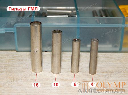
In my practice, I met craftsmen who connected aluminum wires with GML liners. When asked why you are doing this, they replied "well, so is the tin-coated sleeve." In their opinion, due to the tin layer there is no direct contact of copper with aluminum. I still do not advise to do so, because during deformation the upper layer of the liner is broken, and corrosion in this case is a matter of time. Go then, look for where the contact disappeared, the twist can still be examined, and the sleeve will only have to be bitten off.
Aluminum sleeves in the documentation are referred to as HA " aluminum sleeve ", they should be used if aluminum wires are connected.
Combined sleeves or as they are also called aluminum-copper ones, are intended for the butt-joint of copper and aluminum wires. Combined sleeves have the abbreviation GAM and decode the " sleeves of alumo-copper ." Very convenient when, say, you need to build up the wires with the old wiring.
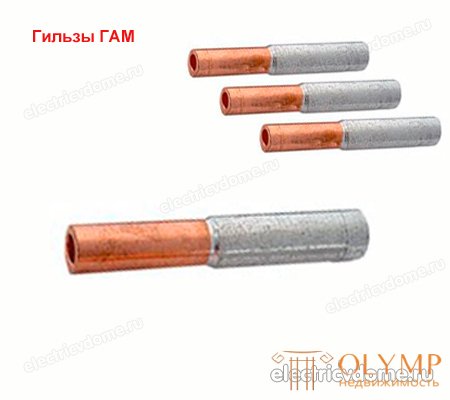
On the one hand, aluminum wire with another copper wire is inserted into the sleeve. In the combined sleeve, the copper part is connected to the aluminum part by friction welding (do not try this at home).
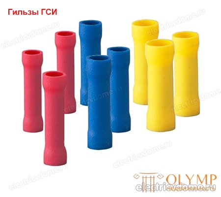
Another type of ICG liner , the abbreviation stands for “ insulated sleeve ”. GSI are a conventional tin-plated sheath, covered with polyvinyl chloride (PVC) insulation. By means of such sleeves copper multicore wires connect. When crimping the wires, the insulation does not need to be removed, the tongs are put on over the insulation and the bench is pressed.
With the type of sleeves figured out, now consider the standard size and range of sections . The minimum cross section that I found on the Internet is 1.5 mm2 (this is for GML). After that, everything goes on increasing 2.5 mm2, 4 mm2, 6 mm2, 10 mm2, etc. In general, sleeves are manufactured with a cross section equal to the standard wire cross section.
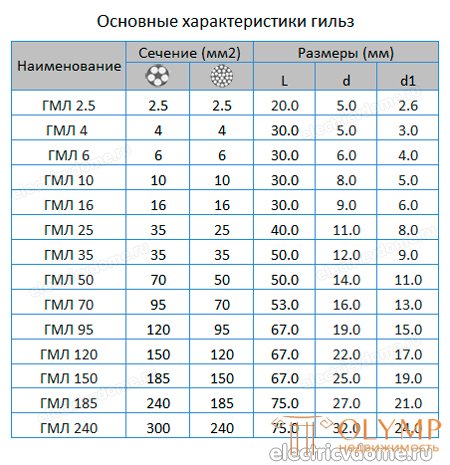
How to read the transcript? For example, GML-6 “tinned copper sleeve 6 mm2”. For liners, GAM is prescribed by a fraction of two numbers - a section on aluminum and a section on copper. For example, GAM 16/10, 16 is the cross section of the aluminum part (in mm2), 10 is the cross section of the copper part (in mm2).
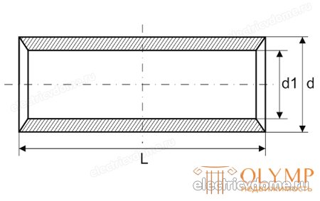
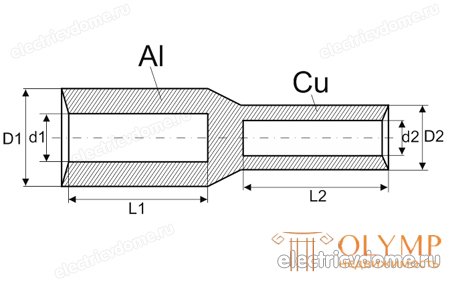
By design, liners are cross-cutting (inside a bare tube) or with a septum (used to connect two end-to-end wires).
Partitions are located in the middle. Thanks to these partitions, the cable entry depth is adjusted, that is, when building up, both ends of the cable will enter the sleeve to an equal length. Such sleeves are used to connect (build-up) the wires to the joint.
Let's try to increase the wire with the help of GSI-6. The wire I will use PV-3, 6 mm2, that is, the section of the sleeve corresponds to the section of the wire. Remove the outer insulation from the wire, insert one end into the sleeve and pressurize. For crimping we use the tested press tongs PK-16 with the corresponding size of the working area of the jaws (6 mm).
We press on top of the insulating layer. We do the same with the second end of the wire, remove the insulation, insert it into the sleeve, and pressurize it. Insulated sleeves for crimping wires covered with PVC insulation and are very convenient in this regard. After crimping, they do not need to be isolated. If you build up wires with ordinary uninsulated sleeves, you can use a heat shrinkable HERE for insulation. I already wrote about how to use such tubes on the site electricvdome.ru, please come in, everyone can read and ask a question.
As you already understood, the sleeves can be used in two ways to connect wires to a joint at the junction (wire build-up) or connecting several wires. Now let's look at how to choose the size of the sleeve for crimping wires on a live example.
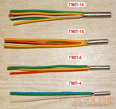
And as an example, we will conduct a small experiment. I'll take a few sleeves of different sections and I will plug them with wires. Look at how many wires, and what section there fit. In our experiment will be involved such shells: GML-4, GML-6, GML-10, GML-16.
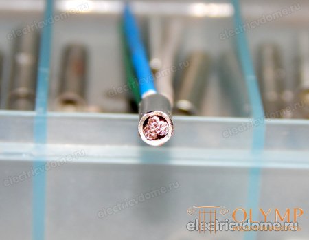
In the four normally comes three wires with a cross section of 1.5 mm2. You can also push two wires of 2.5 mm2 and one for 1.5 mm2. In my case it is. The latter is tight, but you can wear it.
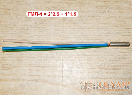
Side view, it can be seen that the sleeve is tightly packed:
The six normally includes four wires with a cross section of 1.5 mm2. If it is necessary to press a larger section, then the six will enter three wires of 2.5 mm2, for sealing one more wire of 1.5 mm2 will enter. 1.5 wire is already tight, but it should be.
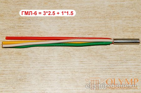
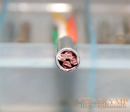
Also in GML-6 will enter one wire with a section of 4 mm2 and two wires with a section of 2.5 mm2.
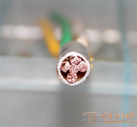
There are four wires with a cross section of 2.5 mm2 and one wire per 1.5 mm2. If we take the wire of a larger section, then from the options in GML-10 it is possible to score two wires of 4 mm2 and two wires with a cross section of 2.5 mm2. Enter tightly. You can also score three wires on 4 mm2 and one on 2.5 mm2. Get in tight.
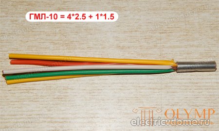
In the photo on the side you can see how many wires are in the sleeve:
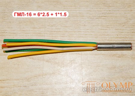
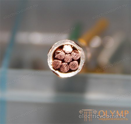
In GML-16 will enter six wires with a cross section of 2.5 mm2 and one wire with a cross section of 1.5 mm2.
And again the photo is as clogged in the sleeve:
To make it clearer, I made a general photo of all copies.
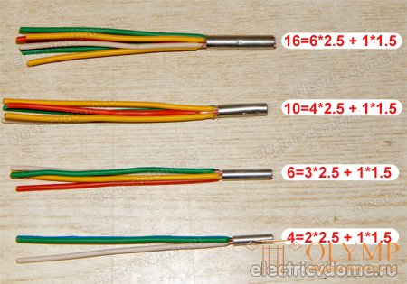
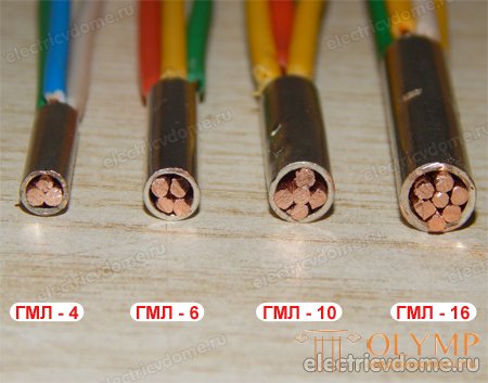
We continue our research. Now we will press all copies and we will try to cut each sleeve. Let's look at pressure testing from the inside. That's what happened.
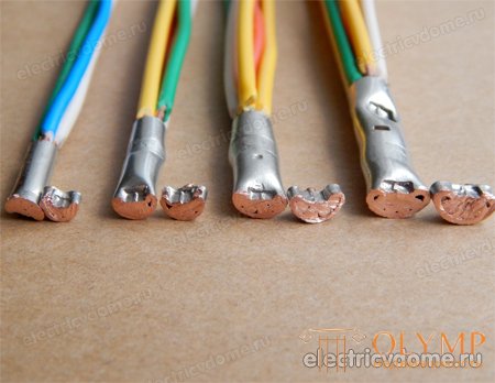
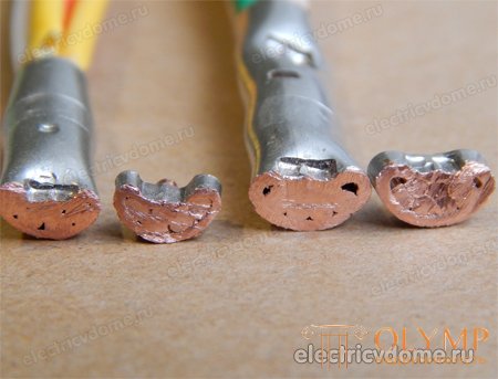
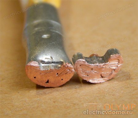
The photo shows that the sleeve is pressed normally, tightly. Well, in principle, that's all. For more my press pincers PK-16 are not capable (I mean the section).
|
|
Что бы оставить комментарий войдите
Комментарии (0)