
Atmospheric and groundwater have a significant impact on the stability of buildings and the durability of buildings. Hydrogeological processes pose a threat of destruction due to the activation of landslide and karst-suffusion movements of the earth's crust. Flooding with groundwater, especially aggressive, causes damage to the underground, parts of houses, creates conditions when the operation of buildings becomes impossible.
Atmospheric precipitation does not only cause premature wear of the ground parts of buildings. At the expense of infiltration into the grades they also feed the aquifers of the rocks, especially the upper ones, since they form the upper layer. Abundant rainfall flooded the city, if not organized or disrupted the discharge of surface water.
Protection against flooding is necessary if the first aquifer from the surface rises to a depth of less than 3 m. At the same time, there is a regulatory gradation, according to which the water should be at a depth of more than 1 m from the floor mark under the basement floor of the submerged building. In areas of green space, the norm is not so tough. For the root system of trees, 1–1.5 m of dry soil is needed and the aquifer can be located at this depth from the ground.
Protection against flooding is resorted to when the territory has a consistently high groundwater level (GWL). It is lowered with the help of drainage systems. They may have perfect and imperfect drains. The perfect ones are immersed before the water seal, that is, the layer that does not allow water to pass through (Fig.10.1.) .

1 - groundwater level; 2 - depression curve;
3 - aquifer; 4 - water stop.
Fig.10.1 - Scheme of groundwater inflow into vertical drains of perfect ( a ) and imperfect ( b ) types
Since the bottom of the drain lies on this layer, the groundwater flows through the side walls. In the drains of the imperfect type, the bottom is located above the impermeable layer, water flows not only from the side but also through the bottom. When pumping water from wells at a rate exceeding its inflow from the ground in the adjacent space, the groundwater level decreases. A depression depression visible in the figure is formed around it. The soil within it is drained.
In Fig. 10.2. vertical drains installed at certain distances and connected by a common pipeline are shown. The step of drains is appointed by calculation, depending on the depth of their immersion, filtration coefficient and other characteristics of rocks. They ensure that the depression funnels overlap each other and the intersection planes are at the height of the required level of aquifer lowering.
Vertical drains - one of the types of water-suction devices. In practice, horizontal drainage systems are often used. The drains are combined with the highway transporting the pumped out water. They are made in the form of trays or perforated pipes sprinkled with coarse-grained material.

Fig. 10. 2. - Design of closed type drains
Game: Perform tasks and rest cool.12 people play!
Play gameThe drains are buried in the aquifer and laid with a slope that provides gravity movement of water to the water intake. An example of such drainage is the system shown in Fig.10.3 a.
In this figure, the drains are laid parallel to the water supply engineering systems. It guarantees against potential flooding with liquid from faulty pipelines. Here the drainage is laid well below them, but sometimes it is placed near these pipelines.
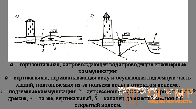
Fig. 10. 3. - Drainage systems
Game: Perform tasks and rest cool.12 people play!
Play game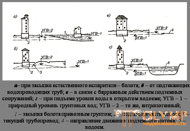
Fig. 10. 4. - The mechanism of flooding areas
Similar systems of horizontal and vertical drainage are suitable for the rise of GWL arising from the backfilling of wetlands and other man-made actions, as a result of which the effect of evaporation of moisture from soils is slowed down (see Fig.10.4 a). The described activities are radical. Their action extends over large areas of built-up areas. However, there are local drainage systems. They are resorted to when they want to provide protection against flooding of one building. Then arrange horizontal belt or reservoir drainage.
Belt drainage pave the outer perimeter of the walls of the basement. At the level of the base of the base is placed perforated pipe-drains. Her bias is assigned to the side of the spillway. The pipe is sprinkled with materials with filtration properties (Figure 10.5 a). They contribute to the drainage system and prevent the particles of shallow soil from clogging the perforations. Such drainage intercepts groundwater coming from the place where the aquifer is fed, and the system’s coverage area is small. Therefore, the drains are trying to lay across the movement of water.
Drainage reservoir divert water directly from under the building. The system consists of a drainage layer, laid under the basement floors. It communicates with external drainage drains. Under the conditions of the old buildings, reservoir drains have specific features. Here, a continuous drainage layer is rarely poured. It is replaced by a system of parallel drains united by a transverse (Fig.10.5 b ).
At the mouth of this drainage make a pit to collect water. It is then dropped into the water removal network from the territory.
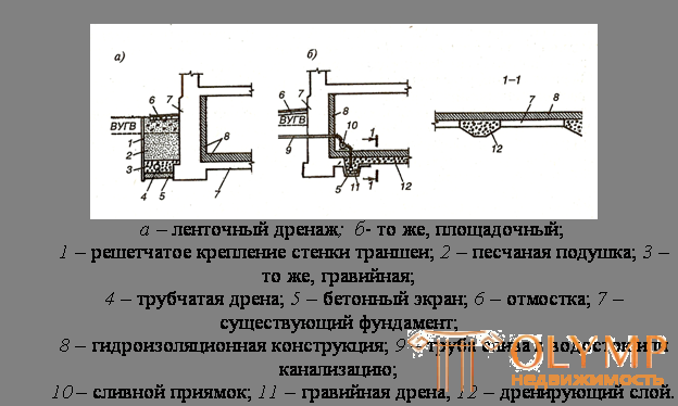
Fig. 10.5 - Water reducing devices used in the repair
Local drainage is, up to a certain point, an effective, albeit expensive, way to protect against basement flooding. However, their device raises the problem of water discharge from drains. The system of gravity, transport directly to the storm net is the simplest. This is possible if the level of its foundation allows you to apply such a solution. Otherwise, it is necessary to create transfer stations and install permanently operating pumps. The functioning of the entire drainage system depends on their uninterrupted operation, therefore the organization of the maintenance service is necessary. The system is not sustainable, since interruptions in the pumping of water will immediately lead to the flooding of the basements.
In addition, pumping water from weak soils is fraught with leaching of small particles of soil, this can lead to weakening of the foundations and subsidence of the foundations. To reduce this effect, drains are sometimes taken to a considerable distance, up to 50 m from the walls, but not less than two depths of immersion of these drains. In this case, it is not the local reservoir that is drained anymore, but a large area, turning the system into regular drainage.
Under the conditions of the old buildings, such a radical method requires a thorough examination of the foundations and foundations of buildings that fall into the zone of dewatering. In urban planning practice, there are frequent cases when a lowering of groundwater flow rates, carried out without proper justification, causes deformations of the supporting structures of houses, for example, associated with the rapid decay of the tips of wooden piles previously protected by water.
Game: Perform tasks and rest cool.12 people play!
Play gameFiltration sprinkled horizontal drains have low maintainability. For cleaning silted dusting used air cleaning. The film, enveloping the filter or silt that has sucked in it, is destroyed by a stream of air under high pressure. However, such a measure is not always effective. Often it is necessary to dig deep trenches or open the floors of the basements, exposing dusting.
Defects of water-lowering devices are not always associated with a decrease in the water-capturing effect of drains. Destroyed pipes and wells. An indicator of this phenomenon is the continuous flow of soil into the system. The pumps sucking the water out of the rocks fail. Repair and sometimes replacement is required. Therefore, drainage systems are serviced in strict accordance with the rules of technical operation of pressure sewage.
Engineering protection of buildings in unstable areas. Engineering protection measures are carried out when the building is in adverse geological conditions. Then the formation of karst and suffosion dips, landslide phenomena, subsidence of the surface of the territory due to soil compression, pumping of groundwater is possible. In turn, many areas are subject to flooding and flooding.
Game: Perform tasks and rest cool.12 people play!
Play gameTo prevent failures carry out the following activities:
establish the rules of economic activity;
ensure the stability of water regimes;
limit water intake, which can cause a decrease in the level of aquifers in carbonate strata;
the territories are not satisfied with surface water bodies;
monitor the serviceability of water supply networks of engineering communications;
do not allow groundwater levels to rise;
create conditions that exclude hydrodynamic effects on arrays of water-soluble rocks, thereby protecting them from destruction.
They also carry out various engineering measures to increase the stability of especially dangerous areas in the hollow cavities inject mixtures of various materials, mortars and concrete.
They use the traditional methods, which are discussed below as measures that provide an increase in the bearing capacity of the foundations.
Landslide phenomena characteristic of cities located on the rivers of Russia. Landslides are divided into two groups: stable and active, being in preparation for the main shift.
The first group includes landslides, backed by floodplain terraces of rivers, which play the role of a buttress stop, which does not allow the bulk of the rock to move. Such landslides do not require complex engineering measures. It is enough to plan and lay the slopes, eliminate their trimming at the base. To strengthen the soil rationally fitomeliorize the surface by planting trees and grass. Do not load the body of a landslide with additional building or dumping of soil. The soils of the sliding surface should be protected from moisture, which violates the properties of the underlying rocks.
The second group requires the implementation of anti-landslide engineering structures aimed at improving the stability of hazardous areas. Therefore, retaining walls are erected here, including on a deep pile foundation. They create counterbunches that reinforce these walls, using retaining structures shown in Fig.10.6.
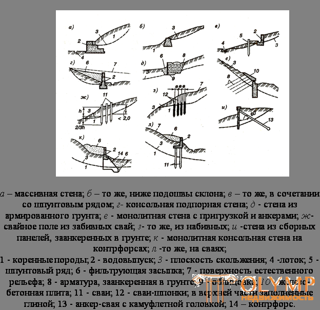
Fig. 10.6. - Retaining walls and pile structures,
small-scale ( a-z ) restraining landslides
Interesting solution, the scheme of which is shown in Fig.10.7. In this project, landslide engineering structures are combined with residential buildings located on the slopes of the existing ravine.
Game: Perform tasks and rest cool.12 people play!
Play gameThe above solution is original, but exclusive. It can be recommended in exceptional cases.
In landslide-prone areas, special attention is paid to the removal of surface water. Create regular gutters. In water-saturated soils, open and closed drainage systems, ditches, galleries and other drainage devices are constructed.
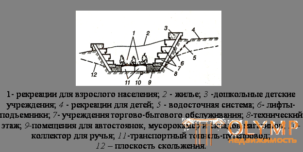
Fig. 10.7. - The project of using the slopes of a ravine for residential construction (section diagram)
Since all these activities do not fully guarantee the possibility of landslide phenomena, create associated drainage along the water-conducting engineering networks and constantly monitor the movement of earth masses.
Game: Perform tasks and rest cool.12 people play!
Play gameIt was established that the precipitation of buildings, the base of which are sandy soils, is small and quickly attenuates. In clay soils, this process develops slowly, but after completion it is characterized by significant drawdowns.
Buildings erected on the cultural layer of bulk man-made soils, undergo significant rainfall. This phenomenon is typical for the central areas of the city, where the bulk layer can reach 15 m. Technogenic soils, as a rule, are not uniform, the thickness of their layer can vary within wide limits. Perhaps the inclusion of lenses of rocks on the density is not relevant neighboring areas. All this leads to uneven precipitation of buildings. .
Unlike uniform subsidence, uneven can cause significant damage to buildings. So, compaction of soft rock layers of different thickness causes the process shown in fig. 10.8, a. There are cases when the weathering of the parent rocks from which the soils originated, proceed selectively. Then under the building there are foundations with different strengths and there are processes similar to the 10.8 a scheme .
No less dangerous lenses of soft soils that have the ability to shrink deformation. Uneven compression of the soil of such lenses leads to the phenomena shown in Fig.10.8, b and c. The incorporation of strong rocks into the foundation, for example, large boulders, causes the building to break according to the scheme of
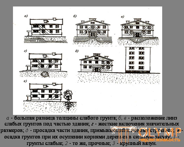
Fig. 10. 8. - Sedimentary deformations of buildings
Groundwater pumping often leads to rainfall over large areas of cities. Removing water from pressure horizons causes not only a drop in pressure, but also a decrease in the levels of aquifers. The compaction mechanism of dried soil is a specific problem that is the subject of hydrogeological studies. It should be noted that due to this compaction, subsidence of the day surface occurs, estimated at 1-150 mm, which leads to partial or complete destruction of buildings. Drawdowns from 10 to 30 mm on average entail deformation in two or three buildings, and when the surface subsides by more than 50 mm, the number of deformed buildings increases.
Drawdowns of structures similar to those described are possible when water interacts with green areas. Some tree species consume large amounts of moisture. Basically it is scooped from the soil of the upper layer moistened with precipitation. With their normal number, the system is in balance. In droughts, the tree in the sandy soil dies, but in the clayey soil it survives. As the drainage of the soil root system develops. Tree roots sprout further and suck the mage out of deep aquifers.
This phenomenon is dangerous for building on soils that have the ability to precipitate with decreasing humidity. In some cases this may cause damage to the building according to the scheme shown in Fig. 10.8 e. Similar phenomena are recorded in a number of cities in the world. Similar processes are observed in the construction of buildings next to existing ones. If the gaps between the old and new objects are small, then drawdowns according to the 10.8 d scheme are possible .
With a uniform drawdown over large areas, a radical re-planning of a quarter, microdistrict or part of it is necessary. This is due to the fact that the streets are being repaired fairly regularly and the processes of ground sedimentation are not so obvious. But between the street sections they are more pronounced. During rains, atmospheric water flows to the buildings. Part of the water flows from streets and lanes falls into residential areas.
Game: Perform tasks and rest cool.12 people play!
Play gameEqually important is the diversion of water from buildings. Another thing is uneven subsidence under the foundations of buildings. They create conditions when it is impossible to continue to use natural soils as bases. There are no guarantees that the building will be in a stable condition in the future. Therefore, before restoring the foundations, carry out activities to strengthen the soil.
Artificial bases are arranged in various ways. Indigenous
rocks with caverns and cracks are strengthened by pumping solutions into them, and concrete into large voids. Sedimentary soils are fixed by electrochemical hardening, roasting, smolizatsii and silicatization.
Electrochemical hardening (электроосмос) основано на физико-химических процессах, протекающих при пропускании через переувлажненный глинистый грунт электрического тока. Под его воздействием происходит необратимая коагуляция глинистых частиц и их закрепление. Кроме того, грунт осушается и, следовательно, уплотняется. Этот метод требует большого расхода электроэнергии.
Game: Perform tasks and rest cool.12 people play!
Play gameСмолuзацuя грунта заключается в его обработке синтетическими смолами, образующими прочные и стойкие кристаллические связи. Метод применяют для закрепления мелкозернистых грунтов при высоком уровне грунтовых вод. Закрепляющие компоненты (смолу и отвердитель) нагнетают в скважины под давлением до 1 МПа.
Сuлuкатuзацuей упрочняют песчаные и пылевидные грунты. Метод заключается в нагнетании химических растворов, которые вступают в реакцию между собой или солями, содержащимися в породе. В результате такой реакции образуется гель кремниевой кислоты, закрепляющий частицы.
В грунты, содержащие соли кальция и магния менее 0,6 мг-экв, нагнетают два раствора – силикат натрия NaSiO2 и хлористого кальция СаСI2. Если же грунты содержат указанные соли более 0,6 мг-экв, то применяют однорастворную силикатизацию. Нагнетают жидкое стекло NаSiO2. Давление, при котором нагнетают растворы, зависит от фильтрующей способности грунта. Чем ниже коэффициент фильтрации К ф, тем должно быть выше давление. При К ф меньше 0,1 м/сут применяют электросиликатизацию. Она отличается тем, что в процессе выполнения работ через грунт пропускают постоянный электрический ток. Он стимулирует перемещение раствора в массе породы. Ток подключают по принципу, изложенному для электроосмоса.
Цементацию грунтов применяют при крупнозернистой их структуре. Сущность метода заключается в инъекциях цементной суспензии, которая закрепляет частицы породы и этим увеличивает его прочность.
Зона закрепления вокруг скважины-инъектора зависит от гранулометрического состава грунта. Радиус проникновения суспензии колеблется в пределах от 0,3 до 15 м. Чем мельче песок, тем меньше радиус укрепленного основания.
Прочность цементированного грунта вблизи скважины достигает 2-3,5 МПа. По мере удаления от инъектора прочность убывает и в крайних слоях – не превышает 0,8-1 МПа. Расход цемента составляет 20-40% от объема закрепляемой породы.
Recently, installations have been used to strengthen soils based on the method of applying under very high pressure, from 25 to 60 MPa, air and cement liquid or mortar, and sometimes water, therefore, it is called the method of water-air jet. The use of air and water in the process contributes to the active loosening of the rock, which provides better penetration of the cement gel into its thickness.
This method allows you to strengthen the soil, to create rigid pillars with a diameter of 0.8 to 2 m. For single-pipe pillars with a diameter of up to 0.6 m, single-pipe systems are used (Fig. 10.9 a). Cement liquid or solution is mixed with air and ejected in the form of pulp through a nozzle at high speed. This jet imparts rotational motion.
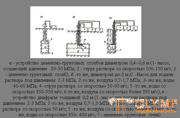
Fig. 10.9. - Water - air method of compaction of grounds
Under the action of such a jet, the sedimentary rocks are loosened to such an extent that the cement penetrates into their thickness, mixing with soil particles. If the rock has a coarse-grained structure, it is enough to supply a cement liquid, but in fine-grained soils it is necessary to add sand, that is, the supply of the solution.
The sequence of fixing the soil in height is provided by the reverse vertical movement of the pipe with a nozzle. In this case, the speed of movement is set depending on the structure of the rocks.
Game: Perform tasks and rest cool.12 people play!
Play gameIn all cases, possible deep consolidation of rocks, about 15-20 m from the surface of the earth.
The strength of fortified pillars depends on the nature and composition of the rocks. The greater the permeability, the higher the strength of the column. It can reach 6-7 MPa in coarse sands and fall to 0.15-0.25 MPa in clay and clay soils.
Foundation reinforcement buildings located on deformed grounds, it is necessary to restore solidity and the initial strength of structures. An effective means of monolithing the walls of strip foundations is to enclose them in reinforced concrete shirts (Fig. 10.10 a, 6). They are important to include in collaboration with the old foundations. To do this, the opposite walls of the cages are fixed between themselves with anchors made of reinforcing steel or channel and I-beams. Simultaneously with the installation of shirts, the weathered laying of old foundations is restored. Cement mortar is injected into cracks and voids. When damage is found in the lower banquets, they are reinforced by longitudinal reinforced concrete beams. If necessary, this allows you to increase the area of support on the base to improve the transfer of load on these beams often set transverse buttresses (Fig. 10.10 c).
Game: Perform tasks and rest cool.12 people play!
Play gameIn places of significant deformations of buildings, columnar foundations are often turned into strip ones. Between the columns erected reinforced concrete wall (as shown in Fig. 10.10 g). It mates with existing pillars, clamps or anchors. If traces of weathering or cracks are found in old structures, they are put into reinforced concrete clips.
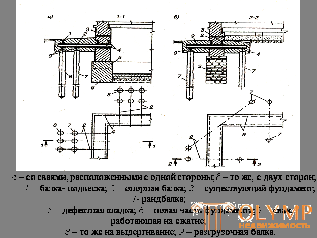
In cases where the soils of the foundations are not able to fully absorb the loads from the foundations, external piles are suitable. They are carried out hanging or relying on deep, hard geological rocks, but in all cases these piles are not clogged. In order to avoid the destruction of buildings from vibration, the indentation method or the air jet method is used.
The pile heads are united by a grillage. Provide reliable interface with the existing foundation. To do this, special beats establish random beams or lay rigid strapping belts (Fig.10.11).
In buildings deformed due to uneven precipitation, it is important to restore the spatial rigidity of the carrier box. With the loss of stability of the walls and their deviation from the vertical resort to the device strapping belts. These belts count on tensile forces. Belts are mounted vertically or horizontally. The first type consists of vertical channels and round steel strands. The channel is laid on the walls or embedded in the penalties. Tie laid in the thickness of the ceiling. The bottom row is set at the level of overlap above the basement or cutting off the walls at the foundations. For inclusion in the work of these strands are straining. Tighten threaded connections.
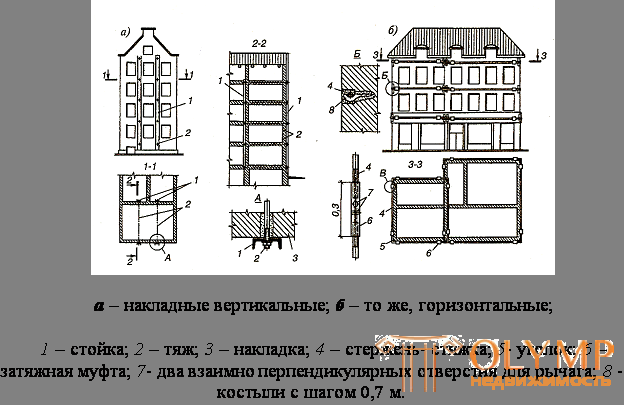
Fig. 10.11. - Belts, reinforcing the wall framework of the building
Belts of the second type - horizontal - make closed. They are placed in the plane of the overlap and consistently strain from the bottom up with special couplings. Apply and electrothermal tension. It is based on the fact that when heated, the metal is extended and the belt in this position is fixed. When cooled, their length is reduced and the strapping, like a hoop, tightly wraps the walls.
Что бы оставить комментарий войдите
Комментарии (0)