6.1. Physical - optical measuring devices
The second way to measure the length of the lines is to use a physico-optical device. The length of the line is determined as a function of the angle at which the basis is visible (optical range finders), or as a function of time and speed of propagation of electromagnetic waves between the end points of the measured line (electromagnetic range finders).
An advantage of physico-optical range finders is the speed of measurements, high accuracy and the ability to measure large distances without preparing the route: all that is needed is optical visibility between the end points of the line.
The idea of optical range finders is based on solving a parallactic triangle, in which the small (parallax) angle β and the opposite leg (base) B determines the distance D by the formula
D = B ∙ ctg β
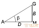
Fig. 55. Parallactic triangle
One of the quantities ( B or β ) is taken constant, and the other is measured. Depending on this, optical range finders are distinguished with a constant base and a variable angle or with a constant angle and a variable base.
6.2. Optical range finder
The most common is a string range finder with a constant parallax angle. It is very simple in design and is available in the telescopes of all geodetic instruments. The grid of threads of such pipes, in addition to the main vertical and horizontal threads, has additional strokes (threads), called distance measuring. With their help, the distance D between the points of the terrain is determined by the distance rod (Fig. 56)
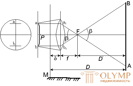
Fig. 56. The scheme for determining the distance of the optical fiber range finder
D = D '+ f + δ
where D ' is the distance from the front focus of the lens to the staff, f is the focal length of the lens, δ is the distance from the theodolite's axis of rotation to the lens.
Consider similar triangles ABF and a1b1F (Fig. 56)
Av / AB = f / D '
where ab = P is the distance between the distance measuring filaments, AB = n is the number of centimeter divisions between the distance measuring filaments on the rail. Then
D '= f / P ∙ n
D = D '+ f + δ = f / P ∙ n + f + δ
The ratio f / P is called the rangefinder coefficient and is denoted by K , and the sum ( f + δ ) is the rangefinder constant and denoted by C.
Then
D = K ∙ n + C.
Rangefinder threads are applied so that when centimeter divisions, the rangefinder coefficient is K = 100. Usually with f lens equal to 200 mm P is taken equal to 2 mm, then K = 100.
In modern theodolites, the rangefinder constant C is close to zero, therefore the number of meters in the measured distance is equal to the number of meters in the distance measuring unit
D = K ∙ n = 100 ∙ n .
With K = 100 and n = 124.3 cm, D = 100 ∙ 124.3 cm = 124.3 m.
6.3. Determination of horizontal lines measured by the rangefinder
When deriving the formula D = K ∙ n, it was assumed that the sighting axis was horizontal, and the distance measuring rod was installed perpendicular to it. In this case, we obtain the horizontal distance of the line S = D = K ∙ n .
However, in practice, in most cases, the sighting axis has a certain angle of inclination v (Fig. 57), and as a result, a vertically located rod will not be perpendicular to the sighting axis.
If the rail is tilted at an angle v so that it is installed perpendicular to the sighting axis, then the inclined distance will be equal to
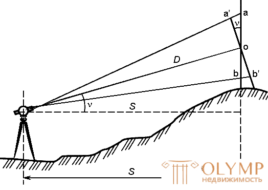
Fig. 57. Scheme for determining the horizontal distance of the line with a thread rangefinder.
D = K ∙ n,
where n '= a'b' = ab ∙ cos ν = n ∙ cos ν .
Then
D = K ∙ n ∙ cos v .
From here we obtain the following formula for calculating the horizontal distance of the line when it is measured with a thread range finder
S = D ∙ cos v = K ∙ n ∙ cos2 v.
The accuracy of measuring distances with a thread range finder is low and is characterized by a relative error of 1/300. The following factors affect the accuracy of determining the distance with a thread rangefinder:
1) the thickness of the ranging yarns;
2) air refraction;
3) the time interval between the sampling of the upper and lower threads.
6.4. Determination of the rangefinder coefficient
The coefficient of the rangefinder K is determined by measuring with a rangefinder a distance of 50, 100 and 200 m on the ground (Fig. 58)
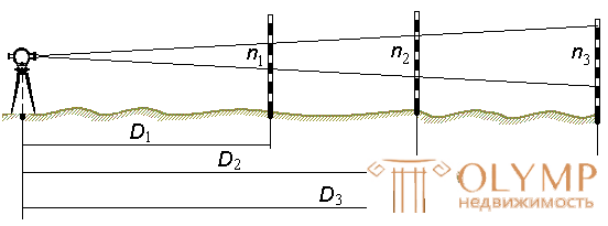
Fig. 58. The scheme for determining the rangefinder coefficient
By the formulas
 ;
;  ;
;  .
.
calculate the three values of the coefficient of the rangefinder and calculate the arithmetic average Kcp .
6.5. The principle of measuring distances by electromagnetic rangefinders
The development of electronics and radio allowed to create new devices for linear measurements - electromagnetic rangefinders (light and radio range finders).
The principle of operation of these devices is based on determining the time interval t required for the passage of electromagnetic waves (light and radio waves) in the forward and reverse direction from point A, in which the device is centered, to point B, where the reflector is installed.
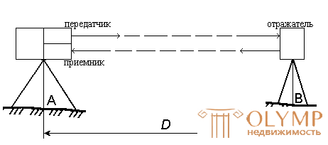
Fig. 59. Scheme for determining the distance by a light-distance meter.
Knowing the speed of propagation of electromagnetic waves, we can write
D = 0.5 · v · t .
Due to the high speed of light (in the atmosphere v ≈ 299710 km / s), the measurement of time t must be performed with very high accuracy. So, to measure a distance with an accuracy of 1 cm, time should be measured with an error of no more than 10-10 seconds.
Measurements are performed by phase or pulse method.
In the phase method, the distances are measured by the phase difference of the emitted and reflected beam. In pulsed - by the time of passage of the laser beam to the reflector and back. The accuracy of measurement depends on the technical capabilities of the rangefinder, as well as on many external parameters: air temperature, pressure, humidity, etc. The distance measurement range also depends on the mode of operation of the rangefinder: reflective or non-reflecting. The measurement range in the non-reflective mode directly depends on the reflective properties of the surface on which the measurement is made. The measurement range on a light smooth surface (plaster, tile, etc.) is several times longer than the maximum distance measured on a dark surface. Maximum range of linear measurements: for a mode with a reflector (prism) - up to five kilometers (with several prisms even further); for non-reflective mode - up to one kilometer.
In the range finder, the laser radiation source periodically sends a light pulse. At the same time, the time pulse counter starts. The counter stops when the remote end receives a reflected light pulse returned by a prism reflector or surface. To improve accuracy, measurements are performed repeatedly. The measured distance is displayed on the digital display.
6.6. Ways to capture the situation
Survey of the situation - geodetic measurements on the ground for subsequent drawing on the plan of the situation (contours and objects of the terrain).
The choice of shooting method depends on the nature and type of the object being filmed, the terrain relief and the scale at which the plan should be drawn up.
Shooting a situation produced in the following ways: perpendiculars; polar; corner serifs; linear serif; alignments (Fig. 60).
Ways of shooting a situation:
1) perpendicular method;
2) polar method;
3) the method of angular serifs;
4) linear serif method;
5) alignment method.
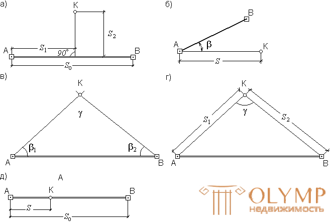
Fig. 60. Methods of shooting a situation:
a - perpendiculars, b - polar, in - angular serifs, d - linear serifs, d - gauges.
The method of perpendiculars (the method of rectangular coordinates) - is usually used when shooting elongated contours located along and near the lines of theodolite course, laid along the boundary of the section to be removed. From the characteristic point K (fig. 60, a), they are lowered onto the line A - B of a perpendicular, the length of which S2 is measured with a tape measure. The distance S1 from the beginning of the stroke line to the base of the perpendicular is counted along the tape.
Polar method (polar coordinates method) - is that one of the traverse stations (Fig.60, b) is taken as a pole, for example, station A, and the position of point K is determined by the distance S from the pole to this point and the polar angle β between the direction to the point and the line A - B. The polar angle is measured by a theodolite, and the distance by a range finder. To simplify the angles, theodolite is oriented along the side of the turn.
In the method of serifs (bipolar coordinates), the position of the terrain points is determined relative to the points of the imaging justification by measuring the angles β1 and β2 (Fig. 60, c) - angular intersection , or distances S1 and S2 (fig. 60, d) - linear serif .
Angular serif is used for shooting remote or hard-to-reach objects.
Linear serif - for shooting objects located near the points of the shooting justification. In this case, it is necessary that the angle γ, which is obtained between the directions during serif, is not less than 30 ° and not more than 150 °.
Way alignments (measurements). This method determines the planned position of the points with a tape or tape measure (Fig. 60, e). The alignment method is used when shooting points located in the alignment of reference lines, or in the alignment of lines based on the sides of the traverse. The method is used when the extreme points of the line are visible. The result of shooting contours recorded in the outline . Outline called schematic drawing, which is drawn up clearly and accurately.
6.7. Questions for self-control
1. What is the principle of measuring distances with a thread rangefinder?
2. What type of thread range?
3. What formula determines the distance measured by the thread rangefinder?
4. How accurately can the distance be measured with a string range finder?
5. How do you determine the correction for the slope of the line measured by the thread rangefinder?
6. What physical principle is used to measure distances with light and radio distance meters?
7. What is terrain shooting?
8. What are the main ways to capture the situation?
Что бы оставить комментарий войдите
Комментарии (0)