4.1. The principle of measuring the horizontal angle
Angles are usually measured in degrees (degrees, minutes, seconds), less often in radians. Abroad is widely used hail measure angle measurement.
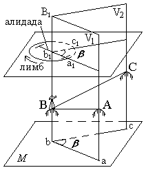
During geodetic works, they measure not the angles between the sides on the ground, but their orthogonal (horizontal) projections, called horizontal angles. So, to measure the angle ABC , the sides of which do not lie in the same plane, you must first project the points A , B , and C on the horizontal plane (Fig. 40) and measure the horizontal angle abc = β (Fig.39).
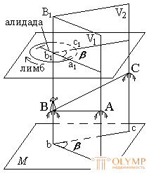
Fig. 40. The principle of measuring the horizontal angle
Consider the dihedral angle between the vertical planes V 1 and V2 , passing through the sides of the angle ABC . The angle β for a given dihedral angle is linear. Consequently, the angle β is equal to any other linear angle whose vertex is located at any point on the sheer edge BB1 of the dihedral angle, and its sides lie in a plane parallel to the plane M. So, to measure the angle abc = β, it is possible at any point lying on the BB1 edge of the dihedral angle, say at point b1 , to establish a horizontal circle with degree divisions and measure the arc a1c1 on it between the sides of the dihedral angle, which will be the degree measure angle a1b1c1 equal to β , i.e. angle abc = β .
4.2. Theodolite, its components
Measurements of the horizontal projections of the angles between the lines of the terrain are produced by a geodetic goniometer using a theodolite . For this, the theodolite has a horizontal angular circle with degree divisions, called a limb . The sides of the angle are projected onto the limb using the mobile sighting plane of the telescope . It is formed by the sighting axis of the pipe when it is rotated around the horizontal axis. This plane is alternately aligned with the sides of the angle BA and BC , sequentially directing the sighting axis of the telescope to points A and C. With the help of a special readout device of the alidade , which is located above the limb coaxially with it and moves together with the sighting plane, the beginning and end of the arc a1c1 (see. Fig. 40) are fixed on the limb, taking samples by degree divisions. The difference of the readings is the value of the measured angle β .
The limb and alidade used to measure horizontal angles form a horizontal circle in a theodolite. The axis of rotation of the horizontal circle alidade is called the main axis of the theodolite.
Theodolite also has a vertical circle with a limb and an alidade, which serves to measure the vertical projections of the angles — the angles of inclination. It is considered to be the angles of inclination above the horizon as positive, and below the horizon as negative. The limb of the vertical circle is usually tightly fastened to the telescope and rotates with it around the horizontal axis of the theodolite.
Before measuring the angles, the center of the limb is mounted on a plumb line through the top of the measured angle using a plumb line or an optical plunger, and the plane of the limb is adjusted to a horizontal position using three lifting screws 3 and a cylindrical level 12 for this purpose (Fig. 41). As a result of these actions, the main axis of the theodolite must coincide with a plumb line passing through the top of the measured angle.
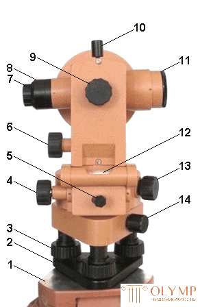
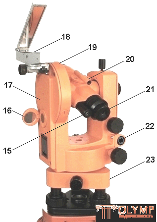
Fig. 41. Theodolite device 4Т30П:
1 - tripod head; 2 - base; 3 - lifting screw; 4 - alidade guide screw; 5 - alidade fixing screw; 6 - telling screw of the telescope; 7 - telescope eyepiece; 8 - a safety cap of a grid of threads of a telescope; 9 - creamer; 10 - anchoring screw of the telescope; 11 - telescope lens; 12 - cylindrical level; 13 - push-button screw for turning the dial; 14 - fastening screw; 15 - eyepiece of a reading microscope with a diopter ring; 16 - mirror for illuminating the strokes of the reference microscope; 17– column; 18 - landmark-compass; 19 - vertical circle; 20 - sight; 21 - telescope eyepiece diopter ring; 22 - cylinder level correction screws; 23 - stand.
For installation, adjustment and guidance of a theodolite on a target, it has a system of screws: stop and lifting screws, clamping (clamping) and guide (micrometrical) screws, correctional (adjustment) screws.
Theodolite is attached to the tripod head with a screw and the lift screws are leveling it.
The fixing screws fasten the moving parts of the theodolite (limb, alidade, telescope) with fixed. The guide screws report a small and smooth rotation to the fixed parts.
In order for the theodolite to provide undistorted measurement results, it must satisfy the appropriate geometrical and optical-mechanical conditions. Actions associated with the verification of these conditions, called verification. If any condition is not met, the instrument is adjusted using correction screws.
4.3. Classification of theodolites
Currently, domestic factories in accordance with the current GOST 10529 - 96 are manufactured theodolites of four types: T05, T1, T2, T5 and T30.
To denote the model of theodolite used the letter "T" and the numbers that indicate the angular seconds of the root mean square error of a single measurement of the horizontal angle.
In terms of accuracy, theodolites are divided into three groups:
GOST 10529 - 96 provides for the modification of accurate and technical theodolites. For example, the theodolite T5 should be manufactured in two versions: with a cylindrical level with a vertical circle alidade and with a compensator replacing this level. A theodolite with a compensator with a vertical circle must additionally be denoted by the letter "K", for example, denoted by T5K.
Technical and operational characteristics of theodolites are constantly improving. The cipher of the updated models begins with a digit indicating the corresponding generation of theodolites: 2Т2, 2Т5К, 3Т5КП, 3Т30, 3Т2, 4Т30П, etc.
According to the design stipulated by GOST 10529 - 96 types of theodolites are divided into repetitive and non-repetitive.
In the case of repeating theodolites, the limb has fastening and suggestive screws and can rotate independently of the rotation of the alidade.
The non-repetitive axle system is provided for high-precision theodolites.
In addition to the design of modern theodolites are divided into: optical-mechanical, optical-electronic and photo-theodolites.
4.4. The main nodes of theodolite
4.4.1. Sampling devices
4.4.2. Levels
4.4.3. Telescopes and their installation
4.4.1. Sampling devices
The counting devices are used to count the limb divisions and assess their shares. They are divided into stroke (theodolite T30) and scale (2T30, T5, 2T5) microscopes (Figure 42) and micrometers (theodolite T2). The angular limb division price is called the limb division value.
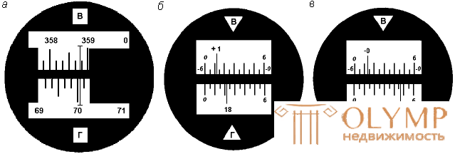
Fig.42. Field of view of reading devices:
a stroke microscope with readings on a vertical circle — 358 ° 48 ', on a horizontal circle — 70 ° 04' ( a ); scale microscope with readings: on a vertical circle - 1 ° 11.5 ', on a horizontal circle - 18 ° 22' ( b ); on the vertical circle - -0 ° 46.5 ', on the horizontal - 95 ° 47' ( in ).
In the stroke microscope of theodolite T30 in the middle of the field of view, a stroke is visible, relative to which the reading is carried out on the limbus (Fig. 42a). Before reading on the limb, it is necessary to determine the price of the limb division. In theodolite T30, the limb division value is 10 angular minutes, since The degree is divided into six parts. The number of minutes is estimated by eye in tenths of the price of the limb division. The accuracy of reference is 1 '.
In the scale microscope of theodolite 2Т30, a scale is visible in the field of view, the size of which corresponds to the division value of the limb (Fig. 42, b, c). For a theodolite technical accuracy, the scale size and the division value of the limb are 60 '. The scale is divided into twelve parts and the price of its division is 5 angular minutes. If the minus sign is not in front of the number of degrees, the counting is performed on a scale from 0 to 6 in the direction from left to right (Fig.42, b). If the number of degrees is preceded by a minus sign, in this case the minutes are counted on the scale of the vertical circle, where the numbers from 0 to 6 are preceded by a minus sign in the direction from right to left (Fig.42). Tenths of the price scale divisions are taken by eye with an accuracy of 30 ".
4.4.2. Levels
Levels are used to bring individual axes and planes of geodetic instruments into a horizontal or vertical position. They consist of an ampoule, rim and adjustment device.
Depending on the shape of the ampoule levels are cylindrical and round. The ampulla of a cylindrical level, the inner surface of which is ground in an arc of a circle of radius R , is filled with heated ether or alcohol and sealed. The liquid-free part of the ampoule filled with liquid vapors is called a level bubble. Strokes are applied on the outer surface of the working part of such an ampoule after 2 mm. The point corresponding to the middle part of the central division of the ampoule is called the zero-point level.
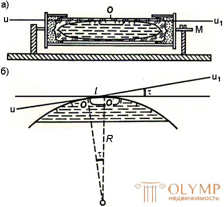
Fig. 43. Cylindrical level
The straight line uu1 - tangent to the inner surface of the ampoule at the zero-point O , is called the axis of the cylindrical level (Fig. 43). At any position of the level ampoule, its bubble will always occupy the highest position, and the tangent to the highest point O 'of the bubble will be horizontal. If we combine the points O and O ', then the axis of the cylindrical level will also take a horizontal position.
The central angle τ corresponding to one division of the ampoule determines the level sensitivity, i.e. the ability of the bubble to quickly and accurately occupy the highest position in the ampoule. The value of this angle is called the price of level division and is calculated using the formula
τ = ρ '' ∙ l / R ,
where R is the radius of the inner surface of the ampoule, mm; ρ "is the radian value in seconds; l is the length of the division of the ampoule, mm.
The more R , the less the price of one division and the more accurate the level. For exact theodolites, the price of level division varies between 15 - 40 "by 2 mm, and for technical ones - within 45 - 60" by 2 mm.
4.4.3. Telescopes and their installation
To observe distant objects in theodolite use a telescope. Surveying instruments, as a rule, supply the Kepler pipe , which gives an enlarged inverted image. Such pipes are called astronomical.
The optics of the simplest telescopes consists of two collecting lenses: an objective (1) aimed at the object and an eyepiece (2). The image is always obtained when the rays pass through the lens, real, reverse and reduced. To enlarge it, an eyepiece is inserted into the tube, acting as a magnifying glass. We receive the imaginary, increased image.

Fig. 44. The telescope: 1 - lens; 2 - eyepiece; 3 - focusing lens; 4 - mesh thread; 5 - rack screw (ring)
Since when viewing at different distances, the image will move, in order to obtain a clear image, it is necessary that the eyepiece can move relative to the lens along the tube axis.
The newest geodetic pipes are supplied with a pipe of constant length, in which the lens and the grid of threads are fixed in one frame. The focusing is performed using a focusing lens (3) - a diffusing glass moving in the tube between the lens and the filament mesh (4) while rotating a special creamer screw or ring (5) enclosing the telescope near its eyepiece.
Simple telescopes have two significant drawbacks: spherical and chromatic aberrations .
The phenomenon of spherical aberration is caused by the fact that the rays of light after their refraction in glass are not collected at the same point, which is why the images of objects are obscure and vague. Spherical aberrations are particularly susceptible to rays falling on the edges of the lens. The colorless rays of light, refracted in glass, decompose into colors and paint the edges of the image in the colors of the rainbow. This phenomenon is called chromatic aberration .
To weaken the spherical aberration take lenses of different curvature, and to eliminate the chromatic aberration of the lens set at some distance from each other.
Full installation of the telescope for observation consists of installing it on the eye and on the subject.
First, an eyepiece is installed over the eye, for which the tube is directed to a light background and the diopter ring is moved so that the mesh threads can be seen sharply outlined. Then the pipe is aimed at the object and its clear image is obtained with a creamer screw, i.e. focus.
After that, the parallax of the grid of threads is eliminated. The point of intersection of the filaments should not descend from the observed point when the eye moves relative to the eyepiece. If it comes down from the observed point, then this phenomenon is called parallax. It comes from the mismatch of the plane of the image of the object with the plane of the grid of threads and is eliminated by a slight turn of the cremallera.
When assessing the quality of the telescope, the following indicators are essential: magnification, field of view and brightness of the pipe.
The magnification of the tube is the ratio of the angle at which the image of the object is seen in the eyepiece, to the angle at which the same object is observed with the naked eye.
Suppose that the eye examines an image of an object in a tube from the center of the eyepiece O1 at an angle β , and the object itself from the center of the lens O at an angle α .
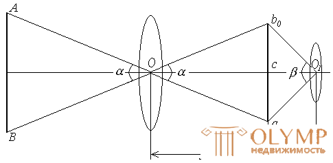
Fig. 45. Enlarging the telescope
When observing over long distances, we can assume that the image of the object in the tube is removed both from the lens and from the eyepiece by the magnitude of their focal lengths, i.e. Oc = fob , and co1 = fok . From the triangles a0O1b0 and a0Оb0 we have

Due to the smallness of the angles α and β , the ratio of the tangents can be replaced by the ratio of the angles, i.e.

Therefore, it can be said that the magnification of the tube is the ratio of the focal length of the lens to the focal length of the eyepiece.
The increase in the telescopes of technical theodolites T30 is equal to 20x, the exact theodolites T5 ranges from 25 to 30x.
The field of view is the space that can be seen through the tube in a fixed position.

From this formula it is clear that the larger the increase, the smaller the field of view. Therefore, for quick guidance on the subject of observation, the telescope is supplied with a sighting tube or an optical sight.
The brightness of the image of the pipe is the amount of light that the eye receives from one square millimeter of the area of the visible image per unit of time. The brightness of the image is directly proportional to the square of the lens hole and inversely proportional to the square of the magnification of the tube. In this regard, during geodetic works, devices with high magnification pipes should not be used, since they have a small image brightness.
4.5. Limit distance from theodolite to the subject
The naked eye can distinguish two distant points if they are visible from an angle of view for about one minute; with a decrease in the angle of view, the points cease to differ and merge into one. Therefore, the error of sight with the naked eye can be considered equal to 60 ". This value of the angle of view is called critical.
When viewing the image in the telescope, the sighting error decreases in proportion to the increase in the pipe and is taken to ± 60 '' / D.
If an increase in the pipe is known, it is possible to calculate the limiting distance from the device to the observed object (Fig. 46).

Fig. 46. The limiting distance from the device to the subject
The limiting angle of view when viewing an image into a pipe is taken to be 60 " / D. Knowing G and diameter S , for example, milestones, it is possible, considering S as an arc of radius D to write: AB = S; S = D ∙ α (in radians)

Dpr = 206265 " ∙ S ∙ G / 60" = 3438 ' S ∙ G.
At T = 20x and S = 3 cm Dpr ≈ 2 km.
The calculated distance should be considered approximate, since the specified formula does not take into account refraction, air transparency and other conditions affecting the observations.
4.6. Questions for self-control
1. Purpose of theodolite.
2. The main parts of theodolite.
3. What are the reading devices in theodolites?
4. The appointment of a cylindrical level in the horizontal circle alidade.
5. Assignment of theodolite telescope.
6. Characteristics of the telescope.
7. What are the installation of the telescope when observing?
Что бы оставить комментарий войдите
Комментарии (0)