Vibrating screens and dispensers . For sifting aggregates (sand, slag, marble and granite chips), as well as binding materials, mechanical vibrating screens are used, to which vibrations are transmitted from the vibrator. Such sieves have high performance, compact and convenient. The sieves are stretched over the frames and, if necessary, easy to replace.
Manual dosing is permissible with small amounts of work. For large volumes, dispensers are used that measure materials in bulk or bulk doses.
Mortar mixers and mortar pumps . For the preparation of solutions used mortar mixers of different designs: CO-23B, CO-46A, CO-26B.
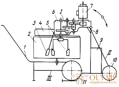
The SO-23B mortar mixer (fig. 85) consists of three main units: the tilting drive I, the carriage II and the replaceable bunker-wheelbarrow III.

Fig. 85. Mortar mixer SO-23B: I - drive, II - trolley, III - bunker-wheelbarrow; 1 - handle, 2 - bunker, 3, 5 - blades, 4 - fencing, 6 - gearbox, 7 - electric motor, 8 - stop, 9 - cabinet with electrical equipment, 10, 11 - wheels
Folding drive includes an electric motor 7, a gearbox 6, on the output shaft of which two rotating blades 5 are mounted and a fixed blade 3 located perpendicular to the gearbox housing. The hinged drive is attached to the trolley and can occupy the working (lowered) and non-working (raised) positions.
The cart is a frame welded from pipes and includes a handle 1, wheels 10 and clamps for mounting the wheels of a bunker-wheelbarrow 2. On the frame is a cabinet 9 with electrical equipment.
The bunker wheelbarrow represents vertically located cylindrical capacity installed on a wheelbarrow.
The volume of the finished mixing of the mixer is 65 l, the power of the electric motor is 3 kW, the mass of the mixer is 65 kg, the capacity is 1.2-1.5 m3 / h. Productivity of mortar mixers СО-46А, СО-26Б-2 m3 / h.
Mechanisms for transporting and applying solutions and bulk materials . Solutions prepared in factories centrally are delivered to the construction sites in the back of cars, on dump trucks, as well as motor transport trucks.
The solution brought in the car bodies at the construction site is discharged into bunkers, from where they are served with mortar pumps on floors or in lifting bunkers, which are transported to floors by lifts. Sometimes the solution is delivered in containers, each of which contains boxes with a capacity of 0.2 m3. The brought container is removed from the machine by crane and the boxes are fed with the help of lifts to the desired floor. At the same time, overload of the solution and its loss are completely eliminated. In winter, the boxes are warmed with removable covers, which makes it possible to maintain a positive solution temperature for 2 hours.
Widely used copyright carriers with batch dispensing of a solution and mechanical stirring on the way and copyright breeders with batch dispensing of a solution, but without mixing during transport.
The mortar pump SO-49B (fig. 86) with a capacity of 4 m3 / h is designed for transporting and applying the solution to the surface at a feed distance of up to 50 m horizontally and up to 15 m vertically. The mortar pump is mounted on a single-axle bogie and is equipped with a pneumatic-electric relay and a protective device for a pressure gauge. The relay is used for remote control, immediate shutdown of the pump motor when the system pressure increases.
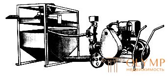
Fig. 86. Mortar pump SO-49B
The mortar pump SO-50 (fig. 87) with a capacity of 6 m3 / h consists of a hopper 2 with a vibrating screen 3, a suction hose 1 from the hopper to the mortar pump, material hoses 6, transition pipes, a ball valve, a nozzle with an annular air supply. The mortar pump pumps the solution horizontally up to 200 m, vertically up to 40 m.
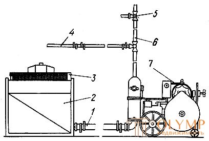
Fig. 87. Mortar pump SO-50: 1, 4, 6 - hoses, 2 - hopper, 3 - vibrating screen, 5 - three-way valve, 7 - mortar pump
Bulk materials are transported to the floors also by pneumatic transport, in which the material moves through pipelines under compressed air pressure.
In the plant for feeding bulk materials (fig. 88), bulk material is loaded into a receiving bin 3, from where it is supplied to pipeline 5 by means of sensor 4 in equal portions. Here it is picked up by an air stream from fan 2 and fed through the pipeline to the right place.
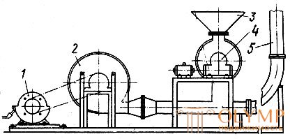
Fig. 88. Installation scheme for the supply of bulk materials: 1 - electric motor, 2 - fan, 3 - receiving hopper, 4 - sensor, 5 - pipeline
Compressors are used for compressed air. The compressor unit consists of the actual compressor, water-oil separator, air collector, pressure regulator and electric motor. Air is sucked into the compressor cylinders through the air filters and valves. From the compressor, compressed air enters first into the water-oil separator, and after filtration, into the air collector, where unfiltered particles of water and oil fall to the bottom.
The compressor is a cylinder with suction and discharge openings. The rotor rotates in the cylinder, the blades of which, taking the air from the suction chamber, compress it in the compression chamber and push it into the air supply hose.
To supply the solution from the mortar pumps and mortar pumps to the workplace, there are solution lines in the form of metal pipes or rubber hoses. The diameter of pipes and hoses depends on the performance of machines and their purpose: mortar (material) hoses have a larger diameter than air (for supplying compressed air).
For pumping a rastovor to the floors of a building, an inventory solution with a single pipe riser or an inventory ring solution pipeline is used as a main pipeline.
Inventory single-pipe dead-end mortar (fig. 89) is mounted from gas pipe segments with a diameter of 50-100 mm, 3 m long, interconnected by flanges 1. To take the solution into floor-standing distribution hoppers or directly to the spray nozzle 4 in the riser on each floor three-way valves 2, a rubber hose is attached to the branch pipe 3 of a three-way valve.
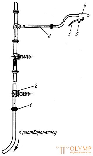
Fig. 89. Inventory single-pipe dead-end solution. 1 - flange, 2 - three-way valve, 3 - branch pipe, 4 - nozzle, 5 - air valve, 6 - air
The annular solution pipeline (fig. 90) is a closed vertical line equipped with floor-standing three-way dispensing taps 2. On the return branch of the solution pipeline there are three-way folding taps necessary for cleaning. One end of the pipeline is connected through a rubber hose to the fitting 3 of the pump, and the other is lowered into the intermediate bunker of the transport installation.
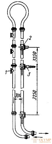
Fig. 90. Annular metal mortar: 1 - revision, 2 - dispensing valve, 3 - fitting
When the mortar pump is operating, the entire line is under pressure and therefore the solution is continuously circulating through the mortar line. In places where the grouting pipes are bent, cranes are installed, pipe joints and rubber hoses are interconnected, often plugs of compressed sand that have separated from the solution are formed. To avoid the formation of traffic jams, it is necessary to monitor the quality of the solutions, the state of the solution lines, eliminate unnecessary bends, prevent wrinkles and bends of the hoses, and perform the joints without narrowing the sections.
The joints of the mortar pipes (Fig. 91) should be arranged so that you can quickly and easily disassemble and assemble these systems.

Fig. 91. Butt joint of rubber hoses of solution pipelines: 1 - rubber hose, 2 - flange with pipe, 3 - rivets, 4 - rubber gasket, 5 - bolt
The nozzles are the tips that are worn on the end of the mortar hose. They serve to spray the solution when it is applied to the plastered surface by various machines. Nozzles are mechanical, or uncompressed and pneumatic. Compressed air as it breaks or sprays the solution into small particles and applies it at high speed to the surface to be plastered. Pneumatic nozzles come with annular and central air supply.
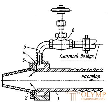
Fig. 92. Nozzle with annular air supply: 1 - fitting, 2 - rubber tip, 3 - nut, 4 - ring bore, 5 - nozzle, 6 - valve
A nozzle with a central air supply (Fig. 93) is sometimes called a universal one, because by changing the distance between the air tube and the tip, the desired spray can be obtained depending on the thickness of the solution and the work performed. When approaching the air tube to the tip of the nozzle gives a wide torch, and when you remove the spray torch narrows. This nozzle can be applied to a solution at a distance of 100-400 mm from the surface, creating, depending on the purpose of the surface to be plastered, different in appearance textures.
All pneumatic nozzles have replaceable tips with openings of different diameters. This is necessary, firstly, because they quickly wear out and have to be replaced, and secondly, for better application of a solution of different thickness.
The use of compressed air when applying the solution requires the installation of a compressor, which complicates and increases the cost of plastering. In the no-compressor nozzles, the solution is applied with increasing pressure in the solution pumps.
Consider several types of uncompressed nozzles.
The nozzle (fig. 94, a) consists of: the body 5, to which the conic nozzle 2 is attached at an angle of 75 °; attached interchangeable cone 6 attached to the body with a nut; cork valve 3 and fitting 4, attached to the mortar hose. The jet of the solution supplied by the mortar pump flows from the conical nozzle into the nozzle body tangentially to its circumference, receiving a rotational helical motion. The speed of movement of the jet of solution in the replacement cone 6 is significantly increased. Under the action of centrifugal force, the jet of solution flies out of the cone opening in the form of a hollow cone-shaped torch with a ring-shaped base. The nozzle is used for applying lime mortar composition of 1: 3, cement-lime 1: 1: 4 and lime-plaster 1: 1: 3.
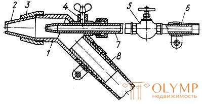
Fig. 93. Nozzle with central air supply: 1 - body, 2 - interchangeable tip, 3 - cap nut, 4 - screw, 5 - valve, 6, 8 - nozzles, 7 - air tube
The other nozzle (fig. 94, b) has a diaphragm 8 in the shape of a circle with a diameter of 40-42 mm, a 10 mm long slit is cut in its center, which is necessary for the solution to exit. The solution is sprayed using this diaphragm. The solution entering the nozzle presses against the diaphragm. The slit of the diaphragm opens and a solution is ejected from it, not by a torch, but by a flat jet 20-30 mm thick and with a maximum width of 500 mm. The slit width determines the length of the jet. The narrower the slot opening, the longer the jet. The diaphragm wears out after plastering 1000-1500 m2 of surface. The performance of the nozzle 800-900 m2 of plastered surface per shift when the thickness of the mortar layer is 6-8 mm. The nozzle is powered by mortar pumps with a capacity of 1-3 m3 / h. The flat stream of solution ejected from the nozzle covers the surface to be plastered without gaps and thickenings. Such a jet is convenient in that it is possible to apply the solution in strips without spraying nearby structures.
The nozzle shown in fig. 94, c, consists of a metal body, a spin-on insert 11 and a nozzle tip 10 with an outlet. The liner is necessary in order to give the solution a rotational motion. After passing through the nozzle, the solution is thrown out by a cone-shaped stream. With a mortar pump with a capacity of 1.5 m3 / h, a nozzle with 9 mm holes is put on the nozzle, and with a mortar pump with a capacity of 3 m3 / h - with a hole of 14 mm. The nozzle weighs 0.5 kg.
The screw nozzle (fig. 94, d) consists of a body, a spray gun 12, an insert 13, a cone-damper 14, a nozzle 2 and a fixed screw 15. The mass of the nozzle is 1.3 kg. Productivity 1000 m2 per shift. The nozzle has several replaceable sprayers with which the size of the torch is adjusted. Passing along the fixed screw, the solution receives a helical rotation and is applied to the surface along a helix, which at the time of contact with the wall has an angle of 15-30 °. The solution is rubbed into the wall, does not rebound and its loss is minimized. This nozzle makes it possible to use a solution of greater rigidity than nozzles of other designs.
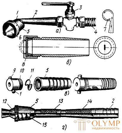
Fig. 94. No-compressor nozzles (a-d): 1 - nut, 2 - nozzle, 3 - crane, 4 - fitting, 5 - body. 6 - interchangeable cone, 7 - direction of movement of the solution in the nozzle, 8 - diaphragm, 9 - handle, 10 - tip, 11 - liner, 12 - sprayer, 13 - insert, 14 - cone-absorber, 15 - screw
No-compressor nozzles have drawbacks: they can be applied only with a draft of a standard cone of 10-14 mm. Thicker solutions clog the hoses and the cone hole, and the thinner ones are stratified. In addition, during operation with such nozzles it is difficult to adjust the length of the spray cone.
For normal operation of the nozzle it is necessary to follow a certain order. When the solution is applied by a pneumatic nozzle, then it must first be started with a stream of compressed air, and only after that - the solution. If, first, the solution is started up in the jet nozzle and then compressed air, a mortar plug may form, causing the pump to stop and requiring disassembly and cleaning of the nozzle.
Plastering units and stations . Plastering units are designed for the preparation of plaster solutions, filtering them, transporting them to the site and applying them to the treated surface. The units consist of a mortar mixer, mortar pump, vibrating screen, lift. All this is mounted on a common frame and air-wheeled chassis. The units produce different performance. The aggregate is attached inventory riser, three-way valve and a set of rubber hoses with a nozzle.
The plastering mobile unit (Fig. 95) is intended for the preparation and transportation of plaster solutions, as well as for their uncompressed application to the surface. The unit includes: a mortar mixer 3, an intermediate hopper 1 with a vibrating screen 4 and a mortar pump 2, hoses and no-compressor nozzles. All this is mounted on a common frame 5 and is driven by a single electric motor.
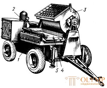
Fig. 95. Plastering unit: 1 - bunker, 2 - mortar pump, 3 - mortar mixer, 4 - vibrating screen, 5 - frame on a chassis
After the unit is installed on the object, the binder and aggregate are manually or mechanically loaded into the mixing drum and water is poured.
The prepared solution is poured through a sieve into an intermediate bunker, from where it flows by gravity into the mortar pump and then through the hoses into floor silos or applied directly to the surface. The ready solution brought from the mortar plants can also be fed into the unit.
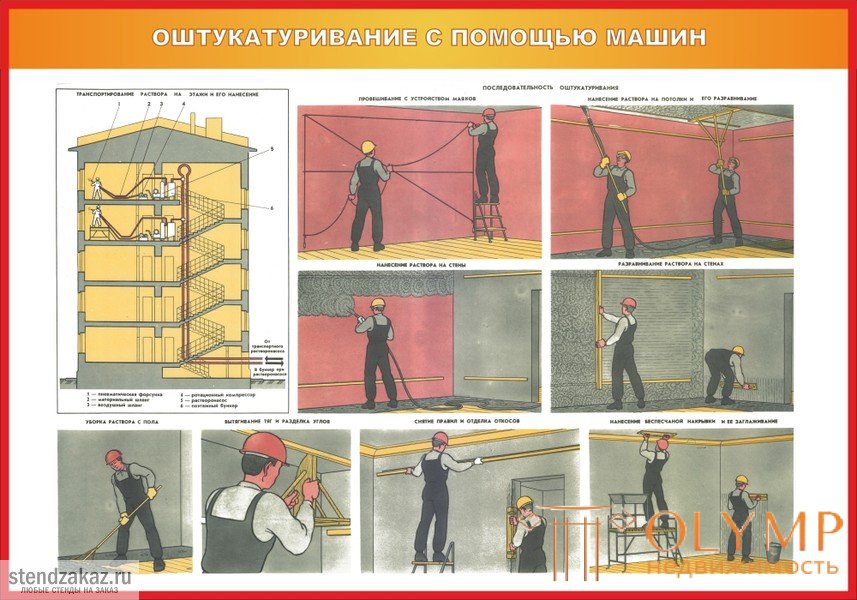
With the help of aggregates, the solutions are fed to the floors as follows (fig. 96). Mortar pumps are installed near the house, which are used to deliver the solution to the floor-standing bunker 3. The solution is pumped over the floors by mortar pumps of low productivity. Depending on the amount of work on one floor, one mortar or several are installed. When plastering with lime-gypsum solutions on the floors, they additionally install mortar mixers for preparing the planting with a retarder. Compressors are located at the mortar site or near the mortar pumps.
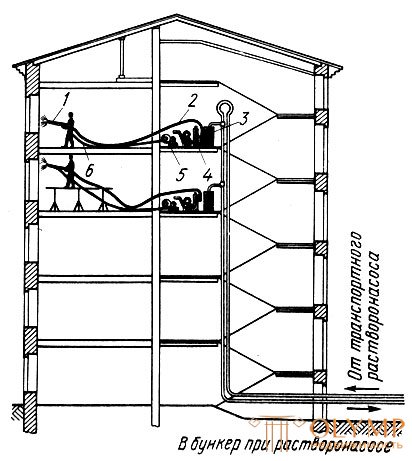
Fig. 96. Transporting the solution to the floors: 1 - pneumatic nozzle, 2 - material hose, 3 - floor bunker, 4 - mortar pump, 5 - compressor, 6 - air hose
Что бы оставить комментарий войдите
Комментарии (0)