7.1. Fixing route height
Along the entire track broken on the ground, but outside the work zone, points are fixed, called rappers . They may be temporary and permanent. Temporary benchmarks are poles buried below the depth of frost penetration. The cross is attached below. Such a benchmark is called a temporary ground. As a temporary frame, you can use the stumps of trees with a diameter of 0.5 m or more. Temporary bench marks are placed on the highway every 2–3 km, and after 20–30 km, permanent bench marks are arranged. Especially it is necessary to arrange them at the beginning and at the end of the route, at stations, near future bridges and tunnels. Permanent benchmarks can be wall or ground.
7.2. Task leveling.
The goal of leveling the route is to obtain picket marks, plus points and cross-section points for building the longitudinal and transverse profiles of the route. It is performed following the layout of the picket and the installation of benchmarks. Leveling lead from the middle with the distance from the level to the rails 50 - 100 m.
The team for leveling consists of a level, a recorder and two rackets.
Brigade equipment includes a level with a tripod, two double-sided slats, two portable latches (shoe), leveling log. It is forbidden to perform leveling without checking the level and slats.
In order not to miss the pickets and plus points, the leveling device should have a route log.
7.3. Work with a level at the station
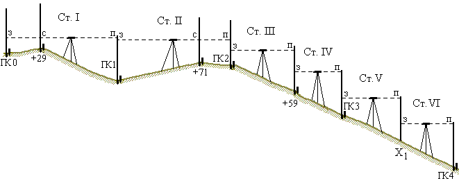
To determine the elevations between the connecting points, at each station the level is set in the middle between them (Fig. 90). They take pickets or plus points as tie points, but so that the distance between them is no more than 150 m, and the elevations are somewhat less than the length of the batten. At the same time, in order to control the excess, two rails with a difference on the red sides of the rails per 100 mm should be included in the kit. For example, one rail with a reference point of 4687 mm, and the second - 4787 mm.
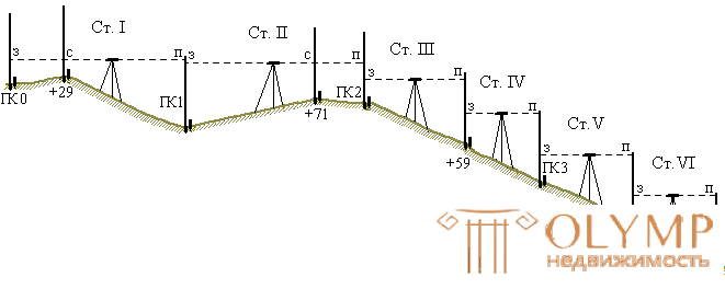
Fig. 90. Track leveling
The readings on the rails installed on the tie points are taken in the following sequence:
1) on the black side of the rail to the back point of the AF ;
2) on the red side of the rail to the rear point of the Cam ;
3) on the black side of the rail to the front point of the FC ;
4) on the red side of the rail to the front point of the PC .
Calculate elevations

If the resulting elevations are equal or differ by no more than 5 mm, then the average excess is calculated from them. Otherwise, the work is being reworked.
Example:

If there are intermediate (relief or contour) plus points between the connecting points, the rear slider alternately puts a rail on them, and the leveler takes the intermediate count C only (on its black side) (Fig. 90 points PC0 + 29, PC1 + 71).
After that, work at the station is completed and transferred to the next one. At the same time, the rear rack from the intermediate point moves to the front point of the new station. The front rack stays in place and will be at the back of the new station.
At the new station and on all subsequent work are carried out in the same manner.
Depending on local conditions, they also take plus points for connecting points. For example, at stations III and IV (Fig. 90), the plus point PK2 + 59 is taken as the link.
On steep slopes, where the excess between the pickets is more than 3 m, it is necessary to put additional tie points. For example, picket PK3 and PK4 lie on a flat steep slope and the excess between them is greater than the length of the slats. In this case, the elevation between the pickets is measured in parts using an additional connecting point, called the x-point . The rail in the x-point is put on a peg or portable shoe. On very steep slopes put a few X-points . They do not put X-points on the profile and do not measure the distances from them to the pickets. They serve only to transfer excesses.
7.4. Leveling ravines
If the leveling course crosses a narrow (up to 100 m) ravine with steep slopes, then in order to avoid accumulation of errors during descent into the ravine and during ascent from it, the height is transmitted immediately from one bank to another (fig. 91).
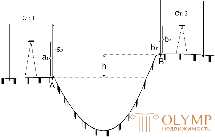
Fig. 91. Leveling over the ravine
To do this, from two stations 1 and 2 level points A and B on each bank of the ravine. The excess between these points is calculated twice:
h1 = a1 - b1,
h2 = a2 - b2.
The discrepancy between the values of h1 and h 2 should not exceed 5 mm.
The transfer of height through wide ravines is done both through rivers. If it is necessary to draw up a transverse profile of the ravine, a picket is broken down with picket sticks and positive points, which are then leveled. Usually leveling down one ravine slope, leveling the points located on both ramps.
Leveling overgrown ravines has to do for each spur separately.
Wide ravines level as well as rivers (Ref. 7.6).
6.5. Leveling Widths
Leveling widths perform in two ways:
1) along the way with the longitudinal leveling of the track; 2) from individual stations, independently.
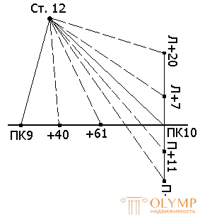
Fig. 92. Leveling Widths
If the widths are leveling along with longitudinal leveling, then the slats are installed on the points of the diameter and take the readings as on intermediate points (Fig. 92).
With a separate leveling level set in such a place that with one station you can read the readings on the rails at the greatest possible number of points of one, two, or even three diameters.
Samples are taken only on the black side of the rail. In this case, the initial (rear) point is the picket or plus point of the route, knowing the height of which calculates the level horizon.
7.6. River leveling
With a river width of up to 150 meters, leveling is conducted in the usual manner, from 150 to 300 m from one bank to another is transmitted as follows (Fig. 93).
On both banks, points A and B are chosen not lower than 2 m above the surface of the water and fixed with temporary reference points. At 50 - 60 m from these points, stations 1 and 2 are chosen so that the lines of st. 1 - A and Art. 2 - B were approximately parallel, and the distances of art. 1 - In and Art. 2 - A are equal.
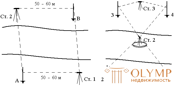
Fig. 93. Leveling of wide rivers
At points A and B put double-sided slats, and at station 1 - level. On the rail at point A, take readings on the black and red side, then take readings on two sides of the slats at point B. Without changing the focus of the level pipe, move across the river, set the level at station 2 and take readings on two sides of the slats at point A and then at point B. The value of the excess of point A over point B is calculated twice and the average is taken if the difference of the excess is no more than 10 mm per 100 m distance.
If there is an island or stranded in the middle of the river (Fig. 93, b), the station is selected on them and with a beam length of up to 100 m is leveled in the usual way.
With a larger length of the sighting beam, points 1 and 2 are fixed on one side, 3 and 4 on the second bank. The level is put on station 1, samples are taken on rails 1 and 2 (on the black and red sides) and transferred to the island on station 2. On the island all four points are leveled, after that the level is transferred to the second bank. From station 3, points 3 and 4 are leveled. To control, two elevation values are found between points 1 and 2, 3 and 4: one from the stations on the coast, the second on the island. If the difference between the elevation values is no more than 20 mm, then the elevations between points 2 and 3, 1 and 4 are found from the readings on the rail taken from station 2 located on the island.
On wider rivers, the mark is passed in a leveling way, laying it through the islands or the bridge located at the side, and in the winter time - on the ice.
14.7. Track Leveling Control
When leveling the track, there may be occasional blunders, for example, miscalculations on the rail or incorrectly installed rail. Therefore, when leveling should be control.
The leveling control of the entire road can be performed in several ways:
1. Leveling between benchmarks with known marks.
If the course is laid between the reference points of the state leveling, then for control, the algebraic sum of ений h exceedances хода h is compared with the difference between the levels of the final Hk and the initial Hn of benchmarks.
Difference  must be no more than acceptable
  mm, where L is the stroke length in kilometers.
2. Leveling in two levels.
The first leveling device levels tie points and intermediate points, and the second goes after it, leveling tie points only. The leveling results are compared daily. With a large difference in elevations perform re-leveling.
3. Reverse positioning.
If the work is conducted by one level, then for control they make a return stroke. During the reverse course only tie points are leveled. Stations where blunders are committed level off anew.
4. Leveling in a closed loop.
Closed is a move that begins and ends at one point. The control is the condition: the algebraic sum of overruns must be zero.
14.8. Questions for self-control
1. What is a bench mark and what does it serve for?
2. What is the order of work at the station when leveling the track?
3. How is the excess determined at the station?
4. What are tie points when aligning a road?
5. When are X-points used in leveling?
6. What are the ways of leveling diameters?
7. How to perform leveling through narrow ravines?
8. How is the mark passed to the other side of the river?
9. What are the ways to control the leveling of the route?
Что бы оставить комментарий войдите
Комментарии (0)