
7.1. Tasks and types of leveling
Leveling is a set of geodetic measurements to determine the elevations between points, as well as their heights.
Leveling is carried out to study the relief, determine the heights of points during the design, construction and operation of various engineering structures. The leveling results are of great importance for solving scientific problems both for geodesy itself and for other Earth sciences.
Depending on the instruments used and the measured values, leveling is divided into several types.
1. Geometric leveling - determining the excess of one point above another by means of a horizontal sighting beam. It is usually carried out with the help of levels, but you can use other devices that allow you to get a horizontal beam.
2. Trigonometric leveling - definition of exceedances using an inclined sighting beam. The excess in this case is determined as a function of the measured distance and angle of inclination, for the measurement of which the corresponding geodetic instruments (tacheometer, kipregel) are used.
3. Barometric leveling - it is based on the relationship between atmospheric pressure and the height of points on the ground.
4. Hydrostatic leveling - determination of exceedances is based on the property of a fluid in communicating vessels to always be at the same level, regardless of the height of the points on which the vessels are installed.
5. Aeroradiation leveling - exceedances are determined by measuring the flight altitudes of the aircraft with a radio altimeter.
6. Mechanical leveling - is carried out using instruments installed in track measuring cars, trolleys, cars, which, when moving, draw a profile of the distance traveled. Such devices are called profilographs.
7. Stereophotogrammetric leveling is based on determining the excess for a pair of photographs of the same terrain, obtained from two points of the basis of photographing.
8. Determination of exceedances from satellite measurements. Using the satellite system GLONASS - Global Navigation Satellite System allows you to determine the spatial coordinates of points.
7.2. Geometric leveling methods
Geometric leveling is the most common way to determine elevations. It is performed using a level that defines a horizontal line of sight.
The device level is quite simple. It has two main parts: the telescope and the device that allows to bring the sighting beam in a horizontal position.
Geometric leveling can be performed according to the following scheme:

Fig. 61. Leveling methods
When leveling from the middle, the level is placed between two points at approximately equal distances (Fig. 61, a). In the points set sheer rails with centimeter divisions. They are put on a peg, hammered flush with the ground, or on a special crutch, since the rake under its own weight will press down on the ground and the reading on it will change. The sighting beam of the telescope of the level is successively induced on the slats and the readings are taken of the S and P , which are recorded in millimeters in the leveling log. Counting on the rail produced by the middle thread of the level, i.e. where the projection of the middle thread crosses the rail. The excess between the points is determined by the formula
h = W - P
where З is counting back to the back point A; P - counting forward to the front point B.
When leveling forward, the device is set above point A (Fig. 61, b), its height is measured V and a readout P is taken from the rail at point B. Excess is determined by subtracting from the height of the device V readout P.
h = V - P.
The height of the anterior point B is calculated by the formula:

The height of the sighting beam on the level surface is called the horizon of the HGI tool (Fig. 61) and is calculated
NGI = ON + Z = ON + V.
The installation location of the level is called a station. If to determine the excess between points A and B, it is enough to install the device once, then such a case is called simple leveling.
If the excess between the points is determined only after a few installations of the level, such leveling is called complex or sequential (Fig. 62).
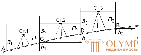
Fig. 62. Sequential leveling.
In this case, points C and D are called binders . Excess between them is defined as with simple leveling:

 ;
;  ;
; 
h = ∑З - ∑П
This leveling scheme is called the leveling process.
7.3. Classification levels
According to the current GOST 10528-90 [9], levels are made of three types: high-precision H-05, precise H-3 (H-3K, H-3KL) and technical H-5 (H-5K and H-5KL).
In the title H - level; 05, 3 and 5 - the standard error of the measurement of the excess in millimeters per 1 km of the double leveling course; K - compensator; L - limb.
Depending on the way in which the sighting beam is placed in a horizontal position, the levels are made in two versions:
- with a cylindrical level with the telescope, with the help of which leveling of the sighting beam is carried out (Fig. 63);
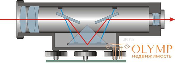
- with compensator - freely suspended optical-mechanical system, which leads the sighting beam to a horizontal position. In the name of the level the letter K stands for a compensator (Н-3К, Н-3КЛ) (fig. 64).
H-3
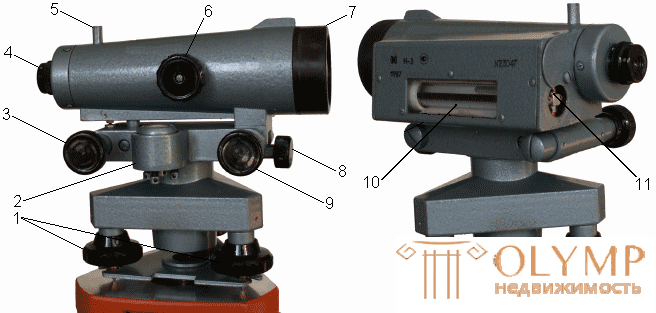
Fig. 63. Exact level Н-3 with a cylindrical level with a telescope: 1 - lifting screws; 2 - round level; 3 - elevation screw; 4 - telescope eyepiece with a diopter ring; 5 - sight; 6 - creamer; 7 - telescope lens; 8 - fastening screw; 9 - suggestive screw; 10 - contact cylindrical level; 11 - cylindrical adjustment screws
The scheme of leveling the sighting beam in the level with a compensator
ZN-3KL
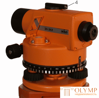
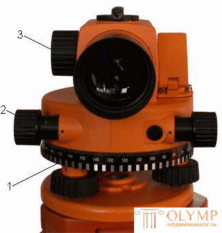
Fig. 65. Exact level ЗН-3КЛ with compensator and limb: 1 - limb; 2 - suggestive screw; 3 - creamer; 4 - reticle.
Exact levels of N-3 and 3H-3KL are intended for leveling classes III and IV.
3H-5KL
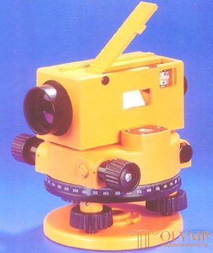
Fig. 65. Technical level 3H-5KL
Technical levels perform technical leveling to determine the heights of high-rise imaging points and when solving various engineering and technical problems in the survey, construction and operation of linear structures and industrial civil engineering.
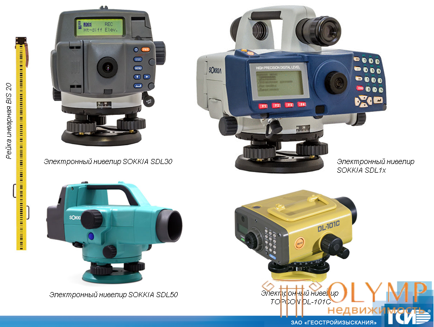
Foreign Levels
SOKKIA
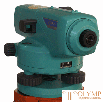
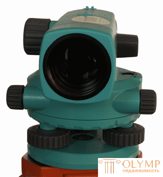
SETL
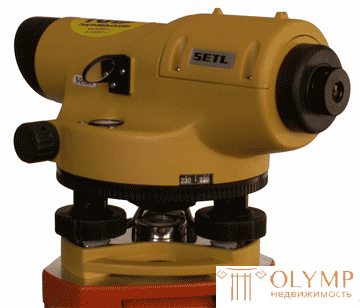
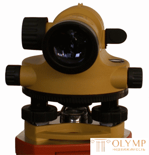
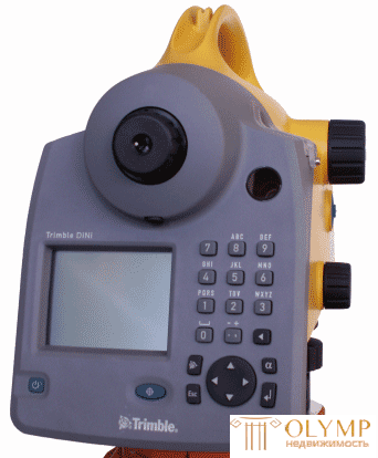
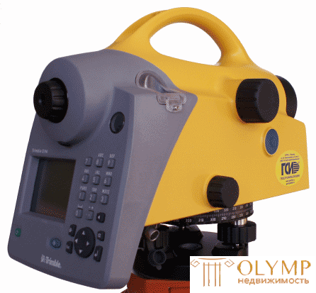
Electronic Levels
Trimble
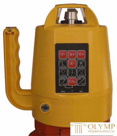
Laser level
7.4. Leveling slats
Leveling slats for leveling III - IV class and technical level are made of wooden bars of I-section 8 - 10 wide and 2 - 3 cm thick.
The PH-3 rail (Fig. 66) has a length of 3 m. The divisions are made after 1 cm. The lower part of the rail is enclosed in a metal frame and is called the heel.
The main scale has black and white divisions, zero is combined with the heel of the slats. The extra scale on the other side of the rail has alternating red and white divisions. With the heel of the slats combined counting more than 4000 mm. Often there are sets of rails, in which the heels of the red sides match the counts 4687 and 4787 mm. Therefore, the elevations measured on the red sides of the rails will be more or less by 100 mm measured on the black sides of the rails.
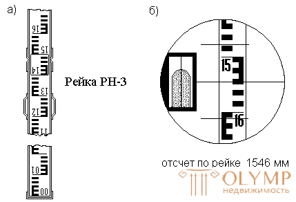
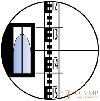
Fig. 66. Leveling rod (a) and the field of view of the telescope level with a cylindrical level (b)
7.5. Influence of the Earth's curvature and refraction on the leveling results
When deriving formulas for leveling methods from the middle and forward, the level surface is assumed to be a plane, the sighting beam is straight and horizontal, the slats installed at points are parallel to each other.
In fact, the level surface is not a plane and the rails installed at points A and B perpendicular to the surface are not parallel to each other (Fig. 67), therefore the readings of H and P are exaggerated by the amount of corrections for the curvature of the Earth SM = K1 and DN = K2 .
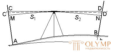
Fig. 67. The influence of the curvature of the Earth and refraction on the results of geometric leveling
Corrections for the curvature of the Earth are:
 ,
,
where S 1, S 2 - the distance from the level to the rails; R is the radius of the earth.
In addition, it is known that a ray of light propagates rectilinearly only in a homogeneous medium. In a real atmosphere, the density of which increases as it approaches the surface of the Earth, a ray of light follows a curve, which is called a refraction curve. As a result, the sighting beam has the shape of a refraction curve of radius R 1 and intersects the slats at points C 'and D'. Therefore, reports on rakes are reduced by the amount of corrections for refraction: СC '= r 1 and DD' = r 2, which are determined by the formula

The radius of the refractive curve depends on temperature, density, air humidity, etc. The ratio of the radius of the Earth R to the radius of the refraction curve R 1 is called the earth refraction coefficient, the average value of which is taken

Denote
 ,
,
where f 1 and f 2 - corrections for the curvature of the Earth and refraction are equal

Therefore, the excess between points A and B, taking into account corrections for the curvature of the Earth and refraction is equal to

The need to take into account the amendment depends on the required measurement accuracy.
From the formula it follows that with equal distances from the level to the rails and approximately the same conditions, we can assume that f 1 = f 2 and h = W - P. Thus, when leveling from the middle with respect to the equality of the shoulders, the influence of the curvature of the Earth and refraction is practically eliminated.
7 .6. Questions for self-control
1. What is called leveling?
2. What are the types of leveling?
3. What are the methods of geometric leveling?
4. What is the leveling method from the middle and forward?
5. What is the essence of sequential leveling?
6. What is the essence of trigonometric, barometric and hydrostatic leveling?
7. How are levels classified by accuracy?
8. What is the difference between the level of the level of the level with a compensator?
9. When can you ignore corrections for the curvature of the Earth and refraction during geometric leveling?
Что бы оставить комментарий войдите
Комментарии (0)