Heat losses of premises in residential and civil buildings are made up of heat losses through enclosing structures (walls, windows, floors, ceilings) and heat consumption for heating air infiltrating into rooms through leaks in enclosing structures. In industrial buildings take into account other costs of heat (the work of ventilation systems with mechanical impulses, the opening of the gate, etc.).
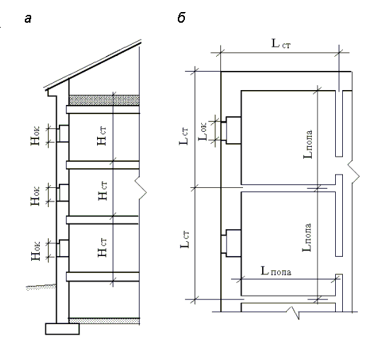
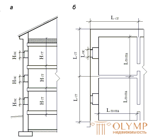 | Heat losses are determined through all enclosing structures and for all heated premises. It is allowed to disregard heat losses through internal barriers, if the temperature difference in the rooms they share does not exceed 3 ° C. Prior to the start of calculations, all premises of the building, in which heat losses must be determined, are assigned numbers. Loss of heat, W, through enclosing structures calculated by the formula Qogr = F (tвn - where F is the calculated area of the enclosing structure, m2; tвн - design air temperature in the room, ° С; tnb - design temperature of outside air, ° С; b - additional heat losses, in shares of the main losses; n is the coefficient taking into account the position of the outer surface of the fence with respect to the outside air; R0 is the heat transfer resistance, m2 · ° С / W, determined by the formula (1.1). The calculated areas of fences are determined according to construction drawings in accordance with the measurement rules given in fig. 1.1. | |
| Fig. 1.1. The scheme of measuring fences: a - in the section of the building; b - on the plan; Nok, Nst, Lst, L floor - linear dimensions of windows, walls and floors |
The estimated air temperature in the room tвн for residential buildings can be taken on adj. 1, and tn B - for adj. 2 depending on the location of the construction object. The values of additional heat losses are given in table. 1.3, and the coefficient n - in the table. 1.4.
Table 1.3
Additional heat loss
Type of fencing | Conditions | Extra heat loss, b |
Exterior vertical walls, windows and doors | When targeting north, east, northeast and northwest; southeast and west | 0.1 |
0.05 | ||
Exterior doors, not equipped with an air curtain at the height of the building H , m | Triple doors with two vestibules | 0.2 N |
Double doors with a vestibule in between | 0.27 N | |
In the corner rooms in addition to walls, windows and doors | One of the fences is facing north, east, northeast or northwest. | 0.05 |
In other cases | 0.1 |
Table 1.4
The values of the coefficient n , taking into account the position of the outer surface of the fence
Type of fencing | n |
External walls and floors in contact with the outside air | 1.0 |
Attic floor | 0.9 |
Overlap over unheated basement with light openings in the walls | 0.75 |
The same without light openings | 0.6 |
Calculations by the formula (1.3) are conveniently performed in tabular form (see example 1).
Heat consumption for heating infiltrating outdoor air in residential and public buildings for all rooms is determined from two calculations.
In the first calculation , the consumption of heat Qi is determined for heating the outside air entering the room through the leakage of fences due to the operation of natural exhaust ventilation in the amount determined by sanitary norms.
In the second calculation , the consumption of heat Qi is determined for heating the outside air that penetrates into the same room through leakages due to thermal and wind pressures in quantity, determined by the values of these pressures. To determine the calculated heat loss by the premises, they take the largest value of those determined by the formulas (1.4) and (1.7) given below.
The first calculation. Heat consumption Qi, W, is determined by the formula
Qi = 0,28 L rвс с (tвн -  , (1.4)
where L is the exhaust air flow rate, m3 / h, taken for residential buildings 3 m3 / h per 1 m2 of living space; rin - the density of internal air, kg / m3; c is the specific heat capacity of air, equal to 1 kJ / (kg · ° C).
Specific gravity g, N / m3, and air density r, kg / m3, can be determined by the formulas:
 , (1.5)
 , (1.6)
where t is the air temperature, ° С; g = 9.81 m / s2.
The second calculation. The heat consumption Qi for heating the outside air penetrating into the room through the leakiness of fences (windows and balcony doors) due to heat and wind pressure is defined as
Q = 0.28 G c (tBH -  ) k, (1.7)
where Gi is the flow rate of infiltrating air, kg / h, through the enclosing structures; k - metering factor of oncoming heat flux, taken for windows and balcony doors with separate bindings equal to 0.8, for single windows and windows with twin bindings - 1.0.
Infiltration of air directly through the wall is very small. Therefore, the value of G i, kg / h, is determined only for windows and balcony doors.
G = 0,216 
 , (1.8)
Where  Pi - air pressure difference, Pa, on the outer RN and the inner surfaces of the RVN windows or doors; SF is the calculated area of fences, separate windows, doors, lamps, etc., m2; Rи - resistance to air penetration of these fences, m2 · h / kg, taken according to [3] or adj. 3
In panel buildings determine the additional flow of infiltrating air through the joints of the panels [2, adj. ten].
The difference in air pressure D , Pa, is determined from the equation
 P = (H - hi) (
  -
-  ) + 0.5
  V2 (Ce, n - Ce, p) k1 - Pint, (1.9)
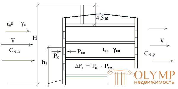 | where H is the height of the building, m, from ground level to the mouth of the ventilation shaft (in confusion-free buildings, the mouth of the shaft is located 1 m above the roof, in buildings with an attic - 4–5 m above the top of the attic floor); The coefficient k1 is taken when the height of the fence above the ground to 5.0 m is 0.5, with a height of up to 10 m - 0.65, up to 20 m - 0.85, more than 20 m - 1.1. The layout of the parameters described is shown in Fig. 1.2. | |
| Fig. 1.2. Diagram of the parameters determining the infiltration of air through a window opening (the symbols are given in explication to the formula (1.9)) |
Calculated heat losses of the room, W, are determined by the formula
Qrach = S Qogr + Qinf - Qbyt, (1.10)
where S Qogr - total heat loss through the fencing of the room;
Qinf is the highest heat consumption for heating infiltrating air from calculations by formulas (1.4) and (1.7); Qbytes - domestic heat generation from electrical appliances, lighting and other heat sources, taken for residential premises and kitchens of at least 10 W per 1 m2 of floor space. The calculation results are entered in the table.
In the training project should perform a detailed calculation of heat loss
3 rooms: corner room on the first floor, another corner room on the top floor and an ordinary room on the middle (in two-story buildings - any) floor. Heat losses of all other rooms are assigned without calculation, while it is necessary to focus on the calculation results of 3 rooms - the heat losses of corner rooms are more than ordinary ones, the heat losses of corresponding rooms on the extreme floors are more than on average ones. All values of heat loss of premises are rounded to tens.
The heat loss of the building as a whole can also be determined by aggregated indicators. The calculation method is given in Appendix. 14.
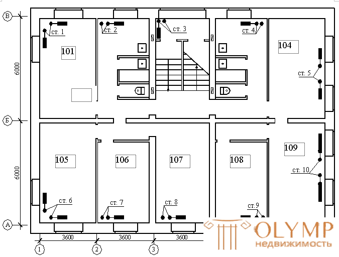 | Example 1. Determination of thermal resistances of enclosing structures and heat losses of a residential building according to the construction drawings shown in Fig. 1.3. Baseline: The construction site is located in the city of Nakhodka. An example of the calculation is given for premises 101 - a corner living room on the first floor. The building in terms of rectangular shape. The basement of the building is unheated, without light openings. Wall and ceiling structures above the basement are given by adj. 3 and shown in Fig. 1.4, 1.5. The window is made with double glazing in separate covers. The orientation of the facade A-A to the north. Decision. By appl. 1 assigned indoor room temperature For the wall adopted the 4th version of the enclosing structure for adj. 3 |
| Fig. 1.3. Plan of the 1st floor (for examples 1 and 2). Room numbers |
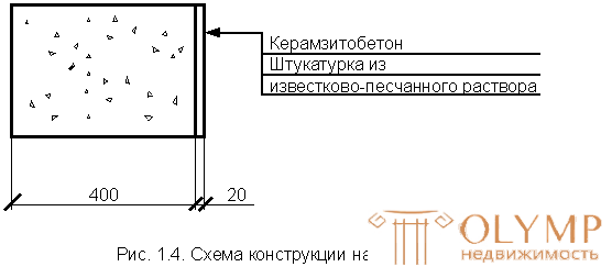
From ADJ. 4, the corresponding values of the calculated thermal conductivity coefficient l are written out. For claydite-concrete l = 0.44 W / m2 · ° С, for plaster on a lime-sand mortar l = 0.81 W / m2 · ° С.
According to the table. 1.1 the values of the coefficients of heat perception and heat transfer of the wall surface Ав = 8.7 W / m2 · ° С and an = 23 W / m2 · ° С are accepted.
Thermal resistance of the wall is calculated by the formula (1.1)
R0 =  m2 · ° C / W.
To overlap above the basement 3 adopted the 1st version of the enclosing structure. According to the difference between the internal and external temperatures, the thickness of the filled layer of expanded clay gravel d = 150 mm is assigned.
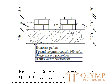
Similar to the previous calculation, the corresponding values of the calculated thermal conductivity of the floor batt are set.
l = 0.18 W / m2 · ° C; expanded clay gravel l = 0.21 W / m2 · ° C, reinforced concrete slab l = 2.04 W / m2 · ° C. Thermal resistance of the air gap is taken from Table. 1.2, with a thickness of 50 mm
Rв.п = 0.17 m2 · 0С / W.
The thermal resistance of the ceiling above the basement
R0 =  m2 · ° C / W.
For the attic floor (Fig. 1.6) 3 adopted the 1st version of the enclosing structure. According to the difference between internal and external temperatures, the thickness of expanded clay gravel d = 150 mm is assigned.
Similar to the previous calculation, the thermal resistance of the attic floor was determined.
R0 =  m2 · ° C / W.
As an illustration of the calculation methodology, the calculation of a flawless overlap is shown (Fig. 1.7). Adopted the 1st version of the enclosing structure for adj. 3
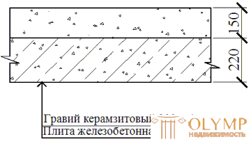 | 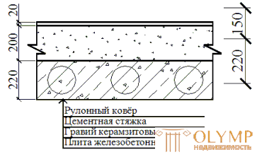 | |
| Fig. 1.6. The scheme of the design of the attic floor | Fig. 1.7. Diagram of the construction of bescherdny floor |
The thickness of the expanded clay gravel is assigned d = 200 mm.
Values of the calculated thermal conductivity coefficient l of expanded clay gravel l = 0.21 W / m2 · ° С, reinforced concrete plate l = 2.04 W / m2 · ° С, cement screed l = 0.76 W / m2 · ° С; av = 8.7 W / m2 · ° С and an = 12 W / m2 · ° С.
Determined by the thermal resistance of flawless overlap
R0 =  m2 · ° C / W.
By appl. 3, in accordance with the difference between the internal and external temperatures, a double-glazed window design in separate bindings was adopted, having the characteristics of R0 = 0.39 m2 · ° C / W, Ry = 0.26 m2 / h · kg.
Calculation of heat loss of premises 101. This room loses heat through two external walls, two windows and the ceiling above the basement. Dimensions of enclosing structures are determined according to construction drawings in accordance with the rules of fig. 1.1 and 1.8. The internal air temperature is assigned to 20 ° C, as for the corner room.
Heat losses through individual enclosing structures are determined by formula (1.3).
|
Fig. 1.8. The scheme for determining the linear dimensions of the room 101: a - plan; b - cut |
Additional heat losses identified b.
According to the table. 1.3 additive on the orientation of the outer wall and windows oriented to the west, b = 0.05; exterior wall and windows oriented to the north, b = 0.1. The additive to the corner room in the presence of a wall facing north is accepted for all walls and windows b = 0.05.
The coefficient n for walls and windows that are in direct contact with the outside air is assumed to be 1, to overlap over an unheated basement without light openings, n = 0.6. The results of all calculations are summarized in table. 1.5.
The value of heat loss for infiltration according to the first method is calculated by the formula (1.4)
L = 3F floor =  m2;
m2;
c = 1 kJ / (kg · ° C);
gвн =  N / m3;
rin =  kg / m3;
Qinf =  W.
W.
To determine the amount of heat loss for infiltration according to the second method, it is necessary to calculate the differential pressure of the air Dp and the flow rate of infiltrating air G. The height of the building to the mouth of the ventilation shaft is set H = 14.3 m, distance from the ground to the top of the window h = 3.3 m; gbn = 11.819 N / m3; gn = 13,688 N / m3; rin = 1,205 kg / m3; Ce, n = 0.8; Ce, p = –0.6;
Pint = 0; V = 7.8 m / s; k1 = 0.5.
Table 1.5
Determination of heat loss of premises
Number of the room | Purpose | Fencing characteristics | tвн, ° С | tвн– - tnБ, ° С | n | R0, m2 · K / W | Extra heat loss | Qogr, W | Qinf, W | Qbyt W | Qrach, W | ||||||
Name | Orientation | Sizes, m | F, m2 | on orientation | to the corner rooms | ||||||||||||
101 | Living room | NS-1 | H | 6.32 × 3.25 | 20,54 | 20 | 40 | one | 1,092 | 0.05 | 0.05 | 828 | 826 | 438 | 2726 | ||
NS-2 | WITH | 3.99 × 3.25 | 12.98 | one | 1,092 | 0.1 | 0.05 | 547 | |||||||||
Window-1 | WITH | 1.8 × 1.5 | 2.7 | one | 0.39 | 0.1 | 0.05 | 318 | |||||||||
Window-2 | H | 1.5 × 1.5 | 2.25 | one | 0.39 | 0.1 | 0.05 | 265 | |||||||||
PP | - | 3.56 × 5.9 | 20.86 | 0.6 | 1,317 | - | - | 380 | |||||||||
SQog = 2338 W | |||||||||||||||||
307 | Living room | NS-1 | YU | 3.6 × 3.25 | 11.7 | 18 | 38 | one | 1,092 | 0 | - | 407 | 780 | 435 | 1512 | ||
Window-1 | YU | 1.5 × 1.5 | 2.25 | one | 0.39 | 0 | - | 219 | |||||||||
PB | - | 3.6 × 5.75 | 20.7 | one | 1,455 | - | - | 541 | |||||||||
SQog = 1167 | |||||||||||||||||
Note NS-1 - outer wall 1; NS-2 - outer wall 2; PP - overlap over the basement; PB - no floor overlap. The remaining notation is described in the formulas to subsection. 1.2, 1.3. Calculated heat loss Qrasch should be rounded to 10 watts.
ΔP101 = (14.3 - 3.3) (13.688 - 11.819) + 0.5 · 1.205 ∙ 7.82 (0.8 + 0.6) 0.5 - 0 =
= 46.218 Pa;
Ginf =  kg / h;
Qinf = 0.28 · 19.51 · 1 (20 + 20) 0.8 = 174.810 watts.
From the results obtained by the two methods, a larger one was chosen - 826.36 W, which will be taken into account in further calculations.
Assigned amount of heat in living rooms 21 W / m2.
Defined household heat in the room
Qbyt = 21 · F floor = 21 · 20.86 = 438.06 watts.
The calculated heat losses of the room are determined by the formula (1.10) Qrass = 2338 + 826 - 438 = 2726 W.
Similarly, the calculation is carried out for other rooms, while you should pay attention to the features of the sizing. As an illustration in the table. 1.5 also shows the calculation of heat loss of an ordinary room 307 on the 3rd floor.
Heat losses of all other rooms of the building are assigned without calculation with reference to the results obtained for two rooms. The staircase is considered as one room with a height equal to the height of the whole building. The results are shown in Table. 1.6.
Table 1.6
Heat loss of the premises of a residential building, W
3rd floor | ||||||||
301 2600 | 302 1500 | LK-1 | 303 1500 | 304 2600 | ||||
305 2600 | 306 1500 | 307 1500 | 308 1500 | 309 2600 | ||||
2nd floor | ||||||||
201 2000 | 202 1000 | LK-1 | 203 1000 | 204 2000 | ||||
205 2000 | 206 1000 | 207 1000 | 208 1000 | 209 2000 | ||||
1st floor | ||||||||
101 2700 | 102 1600 | LK-1 4100 | 103 1600 | 104 2700 | ||||
105 2700 | 106 1600 | 107 1600 | 108 1600 | 109 2700 | ||||
QDit = 53800 W | ||||||||
Thus, the heat loss of the building Qraz = 53800 W is determined.
TEST QUESTIONS
1. What indicator characterizes the heat-shielding properties of fences?
2. How do air gaps in fences affect their thermal resistances?
3. What temperature is calculated when designing heating systems?
4. What factors determine the calculated meteorological conditions in the premises?
5. What heat loss is taken into account when designing heating systems?
6. What factors depends on the flow of air infiltrating into the room?
7. Why is the calculation of heat loss for infiltration produced by two methods?
8. How does the orientation of enclosing structures be taken into account when calculating the heat loss of the premises?
9. How does the geometric dimensions of enclosing structures be determined when calculating the heat loss of the premises?
10. What additional heat loss should be considered when calculating the heat loss of the premises?
11. Compare the heat loss values for infiltration of identical rooms on different floors of a high-rise building.
12. Compare the coefficient of heat perception of the inner surface of the fence and the heat transfer coefficient of the outer surface, why do they not coincide?
13. How does the volume weight of the building envelope material affect the value of the calculated thermal conductivity of the material?
14. How are heat generation in rooms taken into account when calculating heat loss?
15. What are the parameters of indoor air are taken into account when assessing the comfort of the microclimate of the room?
16. In what cases, when calculating the heat loss of premises, should heat flows be taken into account through the internal partitions of buildings?
How is the location of the construction object taken into account when assigning the estimated internal temperature in the room?
Что бы оставить комментарий войдите
Комментарии (0)