The removal of surface waters by vertical planning in built-up areas has its own specifics. Such planning in the conditions of dense buildings is very complicated. Here the prerequisite is the high-altitude linkage of the design elevations of yard areas in two directions.
On the one hand, it is necessary to provide water flow from these sites to the streets, the roadway marks of which are fixed and, as a rule, higher than in the courtyards. On the other hand, the possibilities of vertical planning of inter-trunk areas are very limited. The thickness of the bedding is connected with marks of the blind area of buildings and thresholds of entrance doors to the stairwells. Cutting is also limited, since slopes must ensure the discharge of water to the streets. In addition, the marks of the day surface can be lowered to the limit, excluding the freezing of the base of the foundations and the preserved underground utilities.
Vertical planning in large areas is reconstructed when the planning structure is radically transformed and the quarters are enlarged. They change the network of lanes and courtyards, which were previously diverted surface water.
In areas with a watershed in the form of a hill or ridge, solutions are simple. Here, the elimination of streets does not have a significant impact on drainage. Water can be removed by a saved network of trays at the site of the former passages and reset to the streets washing the buildings.
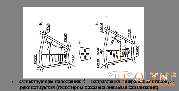
The most complex is the vertical layout of the territories, which are located in the valley or have a deep hollow in relation to the streets. In this case, the technique shown in Fig.10.13 is usually used.

Fig. 10.13. - Scheme of high-altitude solution of systems that divert precipitation in the reconstructed area of significant area
Arrange open or closed drainage systems. Decisions on territories with a general bias, not coinciding with the direction of the saved passages are not less complex. Here also it is necessary to resort to the device of regular drainage systems, even underground.
In the practice of reconstruction often there are yard areas that have
vicious rainwater runoff system. Apply several techniques. They
depend on the reasons, usually associated with the geological processes and man-made activities of citizens.
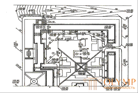
The diversion of water from the courtyard spaces, over the entire area sagging due to inactive suffusion processes, is rather complicated. Requires a thin vertical layout with bedding only in strictly defined places. In the example shown in Fig. 10.14, it was facilitated since the building houses of the 1930s. have at the entrances to the section external stairs of 3-4 steps. It was possible to ensure the removal of water by raising the elevations of passages and passages with a hard surface by an average of 0.3 m. The lawns demanded a local bedding with a vegetable layer of soil.

1 - places in the yard where rainwater accumulated.
Fig. 10.14. - Drainage of water from inter-trunk overgrown territory using the method of vertical planning
Another reason for the lack of effective drainage of water and even its flowing from the streets surrounding the block is the repeated repair of their carriageway. As a rule, these streets are being repaired by laying a new asphalt surface on the damaged old layer. At the same time, the latter is not cut off, and in some streets such a “cultural layer” reaches a considerable thickness, up to 1.5 m. In these cases, the vertical layout is decided by changing the cross-sectional profile of the street, increasing the transverse slopes. Use the fact that repairmen, putting a new asphalt, slightly change the marks of trays.
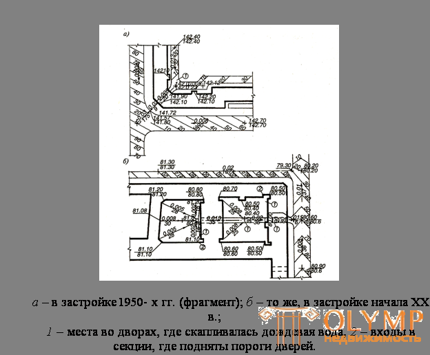
In fig. 10.15, and an example of a vertical solution is shown, which provides water drainage from the courtyard through the arch by streamlining its drain, partially cutting off the tray and pavement at the intersection. Minimal slopes were created in the arch, which made it possible not only to prevent water from entering the street, but also to reset it from internal passages. Such a local solution can often be effective.
Another example is illustrated in Fig. 10.15 b. In the closed courtyards of the beginning of the XX century. water was in many places. Moreover, due to the rise in the repair of the "cultural layer" it flowed to the entrances to the stairwells.

Fig. 10.15. - Drainage of water from domestic areas
A vertical layout removes water from the inner courtyards by creating a gutter along the axis of the arched driveways. As a result, only at two entrances, in the figure marked with index 2, the threshold marks are forcedly raised. This solution turned out to be possible, since in the houses of pre-revolutionary construction the doorways have a height exceeding 2.2 m, and its reduction does not contradict the norms.
Что бы оставить комментарий войдите
Комментарии (0)