The construction of an orthogonal or axonometric drawing, as already known, from the previous section, is based on the use of the methods of parallel projection. The principles of this method are based on the fact that the vanishing point of the projecting lines is conditionally accepted as infinitely distant, which causes parallelism of the projecting lines. In contrast to this phenomenon, the technique is called the method of central projection, if the projecting lines converge into one point, which is reflected in such a phenomenon as perspective. A perspective drawing is a conditional image of an object drawn in perspective. In the practice of educational design, the following two methods of constructing a perspective drawing are used more often.
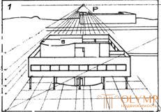
The frontal perspective with one vanishing point is the construction of a perspective drawing in which the picture is parallel to one of the planes of the facade of the depicted object (Fig. 8, 1 ).
This method was first theoretically substantiated by Albrecht Dürer. Durer, obviously, used to build a perspective way of projecting the image on the plane of the frosted glass screen. Placing a rectangular object with respect to the screen so that one of its facades is parallel to the plane of the screen and, putting contours of the object and extending its edges in the form of projecting lines to this plane, you can intersect them at some point P located on the horizon line. If we take into account that all points of the imaged object are on lines that radially converge at the vanishing point P , it is understandable why this method is also called radial. A similar technique for constructing a perspective image using paper overlay on a rigidly fixed vertical frame with a frosted glass screen time was used by artists, researchers to accurately copy the desired object, which replaced in the XVII – XIX centuries. photographic equipment.


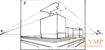
Fig. 8 Building a perspective with one vanishing point (1), with two vanishing points (2)
The basis of the graphic performance of the perspective is a high-quality linear construction, and the best examples of perspective drawings demonstrate not only the exact construction in the lines of the elements of the designed form, but also the preservation of the apparatus of auxiliary and projecting lines. Examples of perspective drawings, made by the method of frontal perspective, are characteristic, above all, for the disclosure of the compositional features of the interior space. Design modeling of the interior space performed by the frontal perspective of the interior using tone and color makes the display of the characteristics of finishing materials, surfaces, furniture panels, etc. as realistic as possible. Such a perspective is carried out using the brush-washing technique or airbrush painting using the gouache and tempera painting techniques. All types of the above technology are impossible without the manufacture of high-quality masks, stencils, patterns of paper, cardboard and synthetic slats. The most common method of graphic construction of a perspective drawing is a linear technique using a rapidograph, identifying its own and falling shadows using the fill, shading, graphic or printing tangier methods. For fillings and hatchings, rapographs with thick needles and felt-tip pens with thick felt are used. Letraset sheets, photo-tangier and applicative films are used to simulate shadows using tangent surfaces.
Angular perspective with one or two vanishing points - the case of constructing a perspective drawing in which the picture is located at a certain angle to the planes of the facade of the depicted object.
Construction with two vanishing points ( F1 and F2 ) - the picture is carried out through one of the edges of the object so that the vertical edge, while remaining in the plane of the picture, retains its full size and, therefore, can be considered a line of natural quantities (Fig. 8, 2 ) . To build the remaining edges of the object, they are moved in the plan in directions parallel to the facades of the object, before being combined with the picture. The resulting points are transferred to the picture and lay natural values of the edges of the building, after which the constructed points are held straight into one of two vanishing points, the intersection of which with the verticals determines the size of each edge.
The required value of verticals in the picture is determined by putting off the segments, taken on the basis of the picture, or from the plan adopted (in orthogonal drawing) and in the picture of the conventional reference point.
Construction with one vanishing point (F1) is similar to the previous one, in which one vanishing point is used for the convenience of construction. The construction is distinguished by the fact that several edges of the form are moved before combining with the picture ( K ), which is done not only to determine their true vertical value, but to obtain a system of points with which the oblique-shaped projections of the facades of the object, which are necessary to build a shape with using the vanishing point ( F1 ).
Что бы оставить комментарий войдите
Комментарии (0)