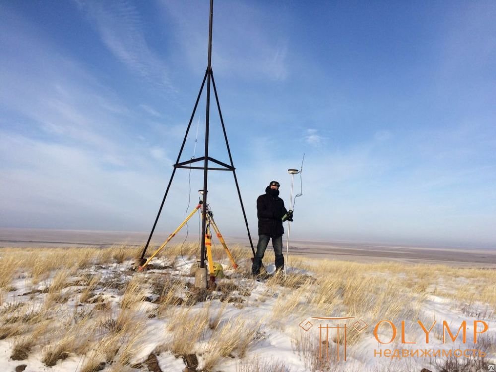
During engineering and geodetic surveys, the geodetic basis of topographic surveys are the strong points of the state geodetic network, leveling and surveying geodetic networks.
The state geodetic network is subdivided into 4th classes and 2 categories of a thickening network. The network of the 1st and 2nd classes is based on a single long-term plan and is the basis for the development of a network of subsequent classes. Work on the construction of the state geodetic network of the 3rd and 4th classes are performed during topographic surveys. The network of the 4th class can be built on topographic and geodetic works and during surveys for construction. The points of the state geodetic network are determined by methods of triangulation, trilateration and polygonometry, or their combinations.
The leveling network is divided into II ... IV classes. Network points are obtained by geometric leveling.
The points of the geodetic survey network are obtained using traverse moves or microtriangulation.
Choosing a place to install characters
The points of the geodetic network, depending on their destination, are fixed with centers or reference points. When designing a geodesic center or a frame, they strive to make it fairly simple, cheap and easy to manufacture, so that it resists well the effects of exogenous forces and, above all, buckling and subsidence.
Practice and special studies have shown that the long-term stability of geodetic points is ensured if the place and depth of the mark is chosen correctly, the center (benchmark) design is most correct for specific conditions and the correct bookmarking method is used. When choosing a place to install a sign, it is necessary to ensure not only the most advantageous conditions for passing the sighting beam, but also to pay attention to the outflow conditions from the surface water sign, to the position of the groundwater level, to the mineral composition of the soil.
If there are outcrops on the surface of rocky soils or when they are close to the day surface, it is advisable to place geodetic centers and benchmarks directly on the rock.
In soft seasonally freezing soils, the most favorable places for laying geodesic points are dry, elevated, turfy plots composed of sandy or sandy loamy soils. Low relief areas, as a rule, create the greatest prerequisites for frosty heaving of signs.
When assigning a depth of laying geodetic points in soft seasonally freezing soils, they are usually guided by the only requirement that the main part of the sign - its anchor - be located in a non-freezing layer of soil. This eliminates the effect on the anchor mark of the most dangerous normal puchuyuschih forces.
If geodesic points are in place, where the subsurface soils are subsided, the anchor must be located in the non-subsidence layer, and under the second type of soil conditions along the subsidence, the pipe leading from the anchor must be protected from the action of negative friction forces.
Constructions of characters
A geodesic mark intended for installation in sandy, loamy and clay soils of seasonal freezing should consist of two parts: an anchor ensuring stability of the mark, and an upper part bearing a point (mark) with known coordinates, or a point (reference) with a known height. The proximity of the mark (rapper) to the surface of the earth facilitates the use of the sign.
An anchor can be either a concrete monolith or a concrete slab weighing about 100 ... 150 kg, with which the upper part of the sign is rigidly connected. The upper part of the sign usually consists of a metal pipe with a diameter of 6 ... 8 cm, in the upper section of which the mark fixing the position of the center or frame is rigidly fixed, fig. 3.1. The brand is closed with a cast-iron cap with a lid.
In undeveloped areas, or where it is impossible to lay a wall sign and, with close proximity of rocks (depth up to 0.8 m), marks are installed whose structures are shown in Fig. 3.2. For their devices in the rock they make a small depression in which the brand is cemented. Above the mark on the concrete cushion set the concrete monolith in the form of a truncated four-sided pyramid. The height of the monolith is assigned such that the mark embedded in its upper base is on the ground level. Top and bottom marks must be on the same vertical.
In the conditions of development, centers that “shoot” or fasten to the wall or base of the building are used to secure geodetic networks, fig. 3.3, 3.4.
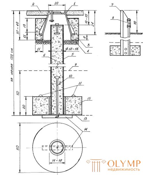
Fig. 3.1. The center of the point of triangulation, trilatherapy and polygonometry of 2, 3, 4 classes, arranged in urban environments
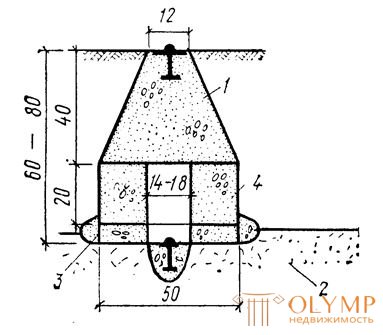
Fig. 3.2. The center of the point of triangulation, trilateration, polygonometry, arranged in rocky soils.
1 - concrete monolith; 2 - rocky soil;
3 - concrete pad; 4 - concrete slab.
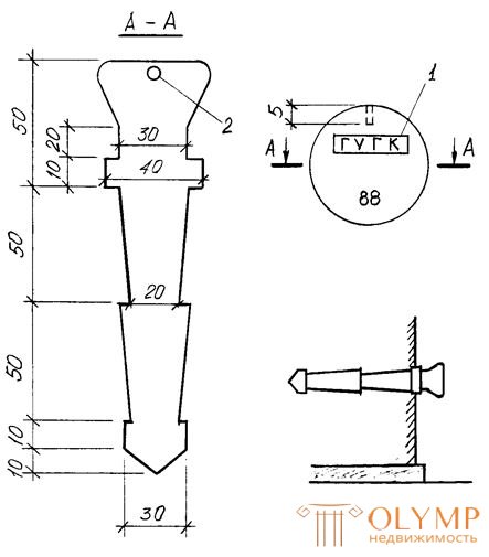
Fig. 3.3. Wall sign item polygonometry 2 - 4th grade.
1 - the initial letters of the name of the organization conducting the geodetic works; 2 - hole for installation of the sighting device.
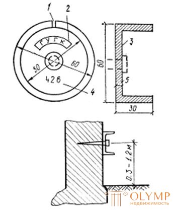
Fig. 3.4. The wall sign of the polygonometry point of the 2nd - 4th grades and the 1st and 2nd digits.
1 - 2 mm hole; 2 - initial letters of the organization (Main Department of Geodesy and Cartography); 3 - glass of mild steel; 4 - number of the sign; 5 - dowel-nail.
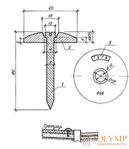
Fig. 3.5. Ground Work Center
1 - dowel-nail; 2 - ball disc; 3 - the initial letters of the name of the organization that installed the sign.
Ground working centers of geodetic networks are fixed by “targeting” them to the road surface or concreting in places without a hard surface, fig. 3.5.
Что бы оставить комментарий войдите
Комментарии (0)