The choice of the method of organizing the air exchange and the type of ventilation depends on the purpose of the building and the premises, as well as on the amount of released hazard. This choice is governed by the rules for the design of the relevant buildings. This manual provides recommendations for the design and calculation of channel ventilation with natural stimulation, most often used in residential buildings, where it is recommended by the norms [1].
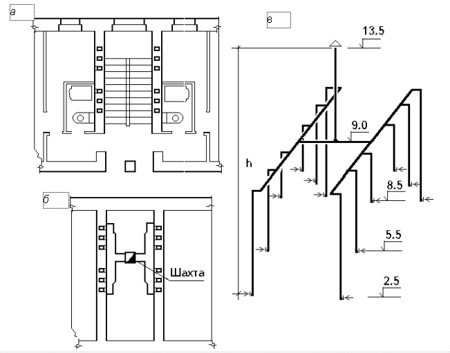
The air is removed from those rooms where the greatest release of hazards occurs. To do this, each apartment provides exhaust channels from the kitchen, bathroom and toilet or a combined bathroom. To remove air from the toilet and the bathroom of one apartment is allowed to use one channel. Air inflow is provided for unorganized through leaks in enclosing structures. Scheme of such a ventilation system, see fig. 4.1, in app. 13 fig. 4, and also [4, § 49].
|
Fig. 4.1. Diagram of a natural channel ventilation system in a building with an attic: a - a plan of the upper floor; b - attic plan; in - axonometric diagram of air ducts with marks of the axes of the channels; h is the distance (in height) from the center of the louvered grille of the first floor to the mouth of the mine |
Air is extracted through louvered grilles installed at a distance of 0.2–0.5 m from the ceiling. Vertical ventilation ducts are suitable only in internal brick walls. The dimensions of such channels must correspond to the size of bricks (140´140 mm, 140´270 mm, etc.). To accommodate the channels, the wall thickness must be at least 380 mm (11/2 bricks). The minimum distance between the channels from homogeneous rooms is half a brick, dissimilar - one brick.
In panel buildings, ventilation is carried out through added or built-in channels in the internal walls and partitions. Circular channels with a diameter of at least 100 mm from asbestos-cement pipes or special ventilation panels can also be taken here.
In chapped buildings, vertical channels are displayed 0.5–1.0 m above the roof and each of them directly communicates with the atmosphere.
In the attic buildings, the vertical channels are combined by ducts, which take the air to the exhaust ventilation shaft, which is displayed above the roof. The mouth of the mine is located 4–5 m above the top of the attic floor.
The building has several independent systems. Since the radius of action of the ventilation system with natural inducement is limited, the distance from the axis of the exhaust shaft to the axis of the outermost channel should not exceed 8 m. Channels and mines are made of materials recommended by the norms [2]: asbestos cement, gypsum board, gypsum concrete, etc.
In fig. 4.1 shows a schematic diagram of the ventilation of a three-storey residential building with an attic, with brick walls and a floor height of 3.0 m. The air in the presented ventilation system is drawn from kitchens and bathrooms. Ventilation of living rooms is also carried out through the hood in these rooms. Adjustable louvered grilles are located 0.5 m below the ceiling surface.
From each ventilated room is its own ventilation channel. Vertical channels are made in the process of laying brick walls. The prefabricated channels in the attic and the shaft are made of slag gypsum. The dimensions of the duct and shaft sections are determined by aerodynamic calculation. In order to avoid condensation of moisture in the channels in the attic, their thermal resistance should be at least 0.5 (m2 × ° С) / W.
From the premises the air is vented to the channels through the louvered grilles, which can be with fixed or movable louvers. The latter allow you to adjust the air flow. Lattices have the standard sizes: 100´150; 150´200; 2´300; 250x350; 300´450 mm and others.


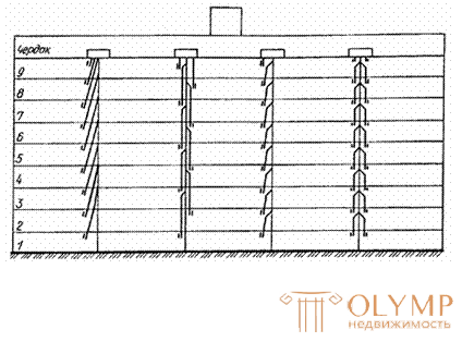
The ventilation system can be mounted from the floor blocks of buildings that are uniform in height. The release of air into the atmosphere is carried out:
a) in cold attic through exhaust shafts, completing each vertical of ventilation units and passing through the attic.
The use of prefabricated horizontal ducts in a cold attic is inevitably associated with an increase in the resistance of the common portion of the ventilation network and, as a rule, leads to periodic disturbances in the circulation of air in the system;
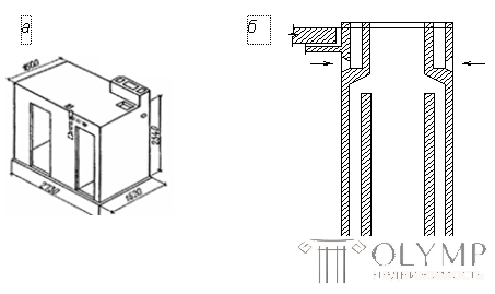
An example of the solution of the combined ventilation unit, combined with the sanitary cabin, is presented in Fig. 4.3.

Fig. 4.3. Combined ventilation unit combined with sanitary ware: a - appearance; b - cut
After making decisions on the design of the system, an axonometric diagram of one of the ventilation systems should be drawn, indicating the elevations of the louvers, channels and the mouth of the mine. Examples of such a scheme are shown in Fig. 4.1, in and in Appendix 13 fig. four.
Что бы оставить комментарий войдите
Комментарии (0)