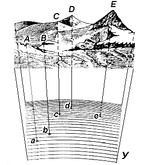
Topographic study of the earth's surface consists in determining the position of the situation and the relief relative to the mathematical surface of the Earth, i.e. in determining the spatial coordinates of characteristic points necessary and sufficient for modeling the terrain. A terrain model can be represented in the form of geodetic drawings, the manufacture of which is called mapping, and analytically - in the form of a set of coordinates of characteristic points. To build terrain models in geodesy, the projection method and various coordinate systems are used.
The horizontal projection method consists in the fact that the studied points ( A, B, C, D, E ) of the terrain with the help of vertical (plumb) lines are projected onto the level surface U (Fig. 5), which results in the horizontal projections of these points ( a , b, c, d, e ). The segments Аa, Bb, Cc, Dd, Ee are called the heights of points, and their numerical values are called elevations.
The height of a point is one of its spatial coordinates. A mark is called absolute if a geoid is taken as a level surface, and relative or conditional if an arbitrary level surface is taken for it.
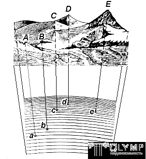
Fig. 5. Designing terrain points on the level surface of the Earth
Two other missing coordinates of a point are determined using a coordinate system built on the mathematical surface of the Earth (Fig. 6).
Two mutually perpendicular planes can be drawn through any point of the reference ellipsoid surface:
Traces of the cross section of the reference-ellipsoid surface by these planes are called the meridian ( M ) and the parallel .
Meridian passing through an astronomical observatory in Greenwich, is called the initial or zero ( M0 ).
A parallel whose plane passes through the center of the Earth O is called the equator ( E ).
The plane passing through the center of the Earth O perpendicular to its axis of rotation PP ' , is called equatorial .
The basis for all coordinate systems are the plane of the Meridian and the equator.
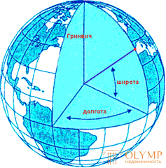
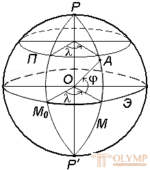
Fig. 6. The system of geographical coordinates
Coordinate systems are divided into angular, linear and linear - angular.
An example of angular coordinates are geographic coordinates (Fig. 6): latitude j and longitude l . Along the corresponding parallels and meridians, the latitude and longitude of the points are constant.
In geodesy, the following coordinate systems are used:
1.5.1. Geodetic coordinates
Geodesic coordinates determine the position of a point on the earth's surface on a reference ellipsoid (Fig. 7).
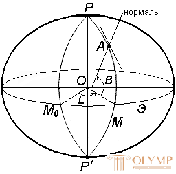
Fig. 7. System of geodetic coordinates
Geodesic latitude B is the angle formed by the normal to the surface of the ellipsoid at a given point and the plane of its equator. Latitude is counted from the equator to the north or south from 0 ° to 90 ° and is accordingly called north or south latitude.
Geodetic longitude L is the dihedral angle between the planes of the geodesic meridian of a given point and the initial geodetic of the Greenwich meridian.
The longitudes of points located to the east of the initial meridian are called the east, and to the west, they are called the west.
1.5.2. Astronomical coordinates (for geodesy)
The astronomical latitude j and longitude l determine the position of a point on the earth's surface relative to the equatorial plane and the plane of the initial astronomical meridian (Fig. 8).
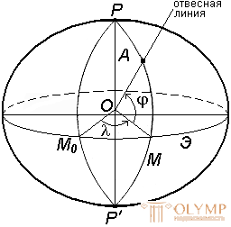
Fig. 8. The system of astronomical coordinates
Astronomical latitude j is the angle formed by a plumb line at a given point and the equatorial plane.
Astronomical longitude l is the dihedral angle between the planes of the astronomical meridian of a given point and the initial astronomical meridian.
The plane of the astronomical meridian is the plane passing through a plumb line at a given point and parallel to the axis of rotation of the Earth.
The astronomical latitude j and longitude l are determined by astronomical observations.
The geodesic and astronomical coordinates are different (differing) due to the deviation of the plumb line from the normal to the surface of the ellipsoid. When compiling geographic maps, this deviation is neglected.
1.5.3. Geographical coordinates
Geographical coordinates - values that generalize two coordinate systems: geodetic and astronomical, are used in cases when the deviation of the plumb lines from the normal to the surface is not taken into account (Fig. 9).
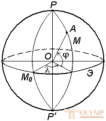
Fig. 9. The system of geographical coordinates
Geographic latitude j is the angle formed by the plumb line at a given point and the equatorial plane.
Geographic longitude l is the dihedral angle between the planes of the meridian of a given point and the plane of the initial meridian.
1.5.4. Flat rectangular geodetic coordinates (zonal).
When solving engineering and geodesic tasks, a flat rectangular geodetic and polar coordinate systems are mainly used.
To determine the position of points in a flat rectangular geodetic coordinate system, the horizontal coordinate plane HOU (Fig. 10), formed by two mutually perpendicular lines, is used. One of them is taken as the abscissa X , the other is taken as the Y axis, and the point of intersection of the O axes is taken as the origin.
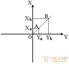
Fig. 10. Flat rectangular coordinate system
The studied points are designed from the mathematical surface of the Earth onto the coordinate plane of the HOU . Since a spherical surface cannot be projected onto a plane without distortions (without gaps and folds), when constructing a flat projection of the mathematical surface of the Earth, the inevitability of these distortions is accepted, but their values are duly limited. For this purpose, the Gauss – Kruger conformal cartographic projection is used (the projection is named after the German scientists who have proposed this projection and developed formulas for its use in geodesy) in which the mathematical surface of the Earth is projected onto a plane by sections — zones into which the entire surface of the Earth is divided by meridians through 6 ° or 3 °, starting from the initial meridian (Fig. 11).
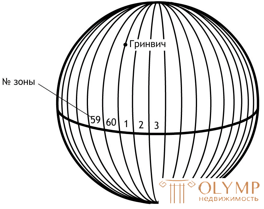
Fig. 11. The division of the mathematical surface of the Earth into six-degree zones
Within each zone is built its own rectangular coordinate system. To this end, all points of this zone are projected onto the surface of the cylinder (Fig. 12, a), whose axis is in the plane of the Earth's equator, and its surface touches the surface of the Earth along the middle meridian of the zone, called the axial one. At the same time, the condition of preserving the similarity of the figures on the ground and in the projection for small sizes of these figures is observed.
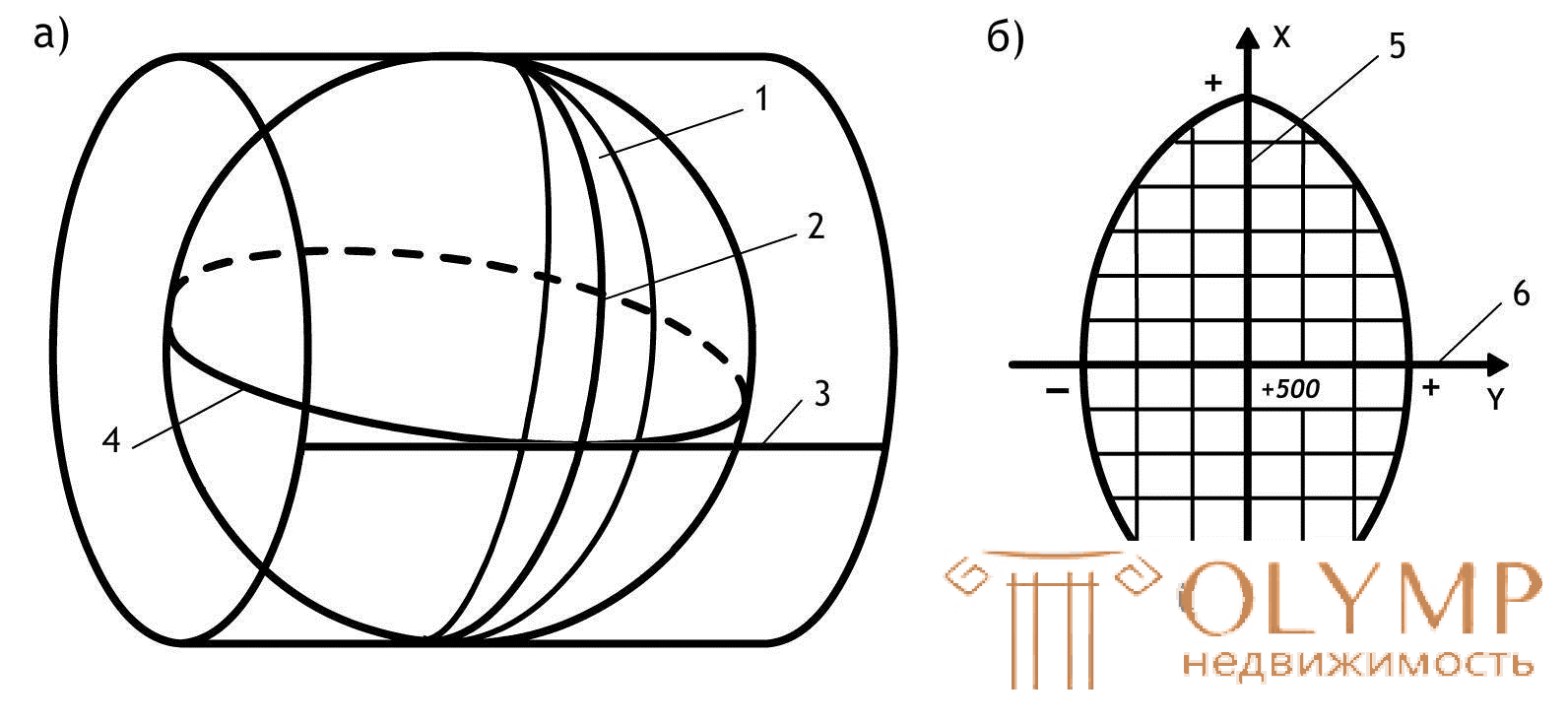
Fig. 12. Gauss-Kruger equipolar mapping projection (a) and zonal coordinate system (b):
1 - zone, 2 - axial (middle) meridian of the zone, 3 - projection of the equator on the surface of the cylinder, 4 - equator,
5 — abscissa axis — projection of the axial meridian; 6 — ordinate axis — projection of the equator
After designing the points of the zone on the cylinder, it expands onto a plane on which the image of the projection of the axial meridian and the corresponding section of the equator will be represented as two mutually perpendicular straight lines (Fig. 12, b). Their point of intersection is taken as the beginning of the zonal flat rectangular coordinate system, the image of the northern direction of the axial meridian is taken as the positive abscissa axis, and the image of the eastern direction of the equator is the positive direction of the ordinate axis.
For all points on the territory of our country abscissas have a positive meaning. In order for the ordinates of the points to be only positive, in each zone the ordinate of the origin is taken equal to 500 km (Fig. 12, b). Thus, the points located to the west of the axial meridian have ordinates less than 500 km, and to the east - more than 500 km. These ordinates are called transformed.
The distortion of the lengths of the lines in this projection increases with distance from the axial meridian to the edges of the zone. At the boundaries of zones within latitudes from 30 ° to 70 °, the relative errors resulting from the distortion of the lengths of lines in this projection range from 1: 1000 to 1: 6000. When such errors are unacceptable, they resort to three-degree zones.
On maps compiled in a Gaussian – Kruger map projection, the length distortions at different points of the projection are different, but in different directions coming from the same point, these distortions will be the same. A circle of a very small radius, taken on a level surface, is also displayed in this projection around. Therefore, it is said that the projection under consideration is conformal, that is, it preserves the similarity of the figures on the sphere and in the projection at the very small sizes of these figures. Thus, the images of the contours of the earth's surface in this projection are very close to those that are obtained.
Quarters of a rectangular coordinate system are numbered. Their count goes along the arrow from the positive direction of the x-axis (Fig. 13).
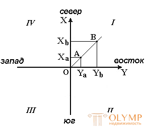
Fig. 13. Quarters of a rectangular coordinate system
If an arbitrary point is taken as the beginning of a flat rectangular coordinate system, then it will be called relative or conditional.
1.5.5. Polar coordinates
When performing surveying and center geodetic works, the polar coordinate system is often used (Fig. 14). It consists of the pole O and the polar axis of the OR , which is assumed to be a straight line with a known beginning and direction.
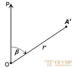
Fig. 14. Polar coordinate system
To determine the position of points in this system, linear-angular coordinates are used: angle β , measured clockwise from the polar axis OP to the direction to the horizontal projection of point A ' , and polar distance r from the pole of system O to projection A' .
1.5.6. Elevation systems
The height of a point is the third coordinate that determines its position in space.
In geodesy, the following elevation systems are used to determine the elevation of points (Fig. 15):
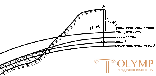
Fig. 15. Systems of heights in geodesy
The orthometric (absolute) height H о is the distance measured in the direction of the plumb line from the geoid surface to the given point.
Geodesic height H g - distance, measured in the direction of the normal from the reference ellipsoid surface to this point.
In our country, all the heights of the benchmarks of the state leveling network are defined in the normal system of heights. This is due to the fact that the position of the geoid under the continents is difficult to determine. Therefore, since the late 40s in the USSR, it was decided not to use the orthometric system of heights.
In the normal system of heights, the elevation of the point H n is measured in the direction of the plumb line from the surface of the quasigeoid close to the surface of the geoid. The difference between the real average sea level and the geoid can reach 1 m.
The quasigeoid (“supposedly a geoid”) is a figure proposed in the 1950s. Soviet scientist MS Molodensky as a strict solution to the problem of determining the shape of the Earth by careful measurements of the gravitational field of the Earth. The quasigeoid is determined by the measured values of the potentials of gravity in accordance with the provisions of the theory of M.S. Molodensky.
In our country, all the heights of the benchmarks of the state leveling network are defined in the normal system of heights. This is due to the fact that the position of the geoid under the continents is difficult to determine. Therefore, since the late 40s in the USSR, it was decided not to use the orthometric system of heights.
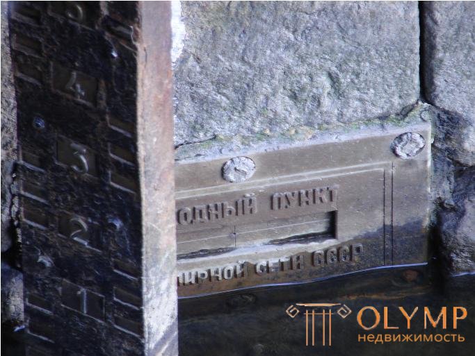
In Russia, the absolute heights of the points are determined in the Baltic system of heights (BSV) relative to the zero of the Kronstadt t -bar - a horizontal line on a copper plate attached to the abutment of the bridge through the bypass channel in Kronstadt.


Relative height H y - measured from any other surface, and not from the main level surface.
The local height system is Pacific, its level surface below zero of the Kronstadt trough by 1873 mm.
1.6. Questions for self-control
1. What is geodesy and what issues does it solve?
2. What is the physical and level surface of the Earth?
3. What is a geoid?
4. What are the dimensions of the ellipsoid F.N. Krasovsky?
5. What is called geodetic latitude and longitude?
6. What coordinate systems are used in geodesy?
7. Explain the essence of the zonal system of rectangular coordinates?
8. What is the absolute and conditional height of a point?
9. What is called a point mark on the earth's surface?
Что бы оставить комментарий войдите
Комментарии (0)