The point method of calculating the lighting is used to calculate the total uniform and localized lighting, local lighting, regardless of the location of the illuminated surface with direct light fixtures. According to this method, the illumination is determined at each point of the calculated surface, relative to each light source. It is not difficult to guess that the complexity of this method is huge! Accuracy is directly dependent on the integrity of the engineer conducting the calculation.
Used to calculate the uneven lighting : general localized, local, inclined surfaces, external. The required luminous flux of the lighting installation is determined on the basis of the condition that at any point of the illuminated surface the illumination should not be less than normalized, even at the end of the service life of the light source.
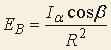
The point method is based on the basic law of lighting engineering, and depending on the light device (point, linear, searchlight) or object characteristics (enclosed room, street, area), the calculation formulas are different.

where Iα - luminous intensity in the direction from the source to the point, cd;
cos β is the cosine of the angle of incidence of the ray on the plane;
R is the distance between the source and the point, m
The calculation of the illumination should be preceded by the choice of the type of lighting devices, as well as the determination of the location and height of their suspension in the room ( hp ), the normalized value of the illumination ( En ) is determined . The calculated point is illuminated by almost all the fixtures in the room, which create a relative total illumination Σe at the calculated point, but the effect of the nearest fixtures is usually taken into account.
It is difficult to determine exactly which lamps should be considered closest and be taken into account in Σe .
In all cases, when determining Σe , luminaires that do not really create illumination at the control point due to its shading by the equipment or by the worker with his normal fixed position at the workplace should not be taken into account.
The points of the illuminated surface in which Σe has the smallest value are selected as the control . You should not look for the smallest illumination (at the walls or in the corners): if there are jobs at such points, the task of providing here normalized values of illumination can be solved by increasing the power of the nearest luminaires or installing additional luminaires.
The definition of e for each control point is made using spatial isoluks of conditional horizontal illumination, on which there is a point with a given d and hp (adj. 6), ( d , as a rule, is determined by measurement according to the floor plan). If the calculated point does not exactly match the isoluks, then e is determined by interpolation between the nearest isoluxes. Spatial isoluxes of conditional horizontal illumination from fixtures with DCC type D-2 are shown in fig. one.
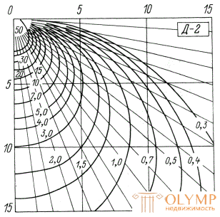
Fig.1. Spatial isoluks of conditional horizontal illumination from luminaires with DCC type D-2
Let the total effect of luminaires create a conditional illumination Σe at the control point; the effect of more distant luminaires and the reflected component are approximately taken into account by the coefficient μ . Then to get at this point of illumination E with the safety factor of the lamp in each luminaire must have a flow:
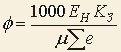
where 1000 lm is the conventional lamp flow;
KZ - safety factor;
Yong - normalized illumination;
μ is the coefficient of additional illumination;
Σe is the sum of the relative conventional illumination from the nearest luminaires, lx.
The sequence of calculation of the lighting installation point method:
It is very important when calculating the luminous flux of the lamps to choose the calculated point correctly. As its on the illuminated surface, within which the normalized illumination should be provided, take a point with a minimum illumination. This point should be taken in the center of the field or in the middle of one side of the extreme field - the space bounded by the four nearest lamps.
Example of calculation by the point method
Example. Calculate the point method of illumination of the room with working surfaces near the walls with the DFC lamps under the following conditions: the calculated height is hr = 4 m , the normalized illumination is Emin = 75 lx , the safety factor is k = 1.5 and the coefficient of added illumination is μ = 1.2 .
Decision. Since the DFC lamp has a deep light distribution, for it λ = 1 . The distance between the lamps we take L = 4m and place them along the tops of the squares 4 × 4 m2. The distance from the outermost lamps to the walls is 0.25L = 1 m . On the floor plan we outline control points A and B , in which the illumination may be the least.
Calculate the distance d from these points to the projections of the nearest fixtures.
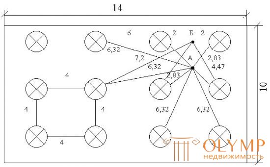
Fig. 2. Design scheme
From the isolux curves for the FDA luminaire, we find the conditional luminosities at the control points from each nearest (accounted) luminaire. For convenience, the results are presented in the form of a table.
For the calculated we take point B as a point with less illumination. The value of Σe for point B is substituted into the formula for calculating the source flux by the point method using the formula and we obtain the required luminous flux of the lamp
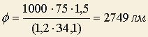
From the table, select the nearest standard lamp G21-235-200. Its luminous flux is φ = 2920 lm and differs from the calculated one by
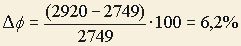
that fits within the limits of tolerances (from -10 to +20%).
Calculation table to determine the conditional illumination (in Fig. 2.)
Number of luminairesDistance d, Conventional illumination, e, lc Number of luminariesDistance d, Conventional luminance, e, lc For point AD For point B42,8330,022,0024,026,322,424,478,026,322,416,001,518,500,317,200,6Σe = 35.1 Σ = 34.1
Что бы оставить комментарий войдите
Комментарии (0)