Content
Since the first node of a branched electrical circuit appeared, it has become necessary to protect both himself from external influences and people from accidental contact with bare conductors.
Already during the first steps of electrification, there was an urgent need to protect the twisting of wires with the help of boxes, which became known as razvetvitelnymi (distribution, raskayachnymi, rasteechnymi, rasklyuchatelnym).
Previously, for these purposes, improvised means were used, as a rule, tin cans. Such an installation was neither fast nor reliable - it was necessary to make holes for the wires, and make sure that they did not damage the torn edges.
The evolution in electrical engineering led to the fact that manufacturers of electrical equipment quickly responded to the need, and began to produce junction boxes of various sizes, types and purposes.
The junction box has many synonyms, in part because of the way the wires are connected inside the box. For example, until recently soldering of wires was considered as the most reliable connection.
Since the voltage from the input cable was distributed between different lines in the junction box by the method of desoldering wires, these boxes were called soldering or crumpled boxes.

Similarly, another term appeared - “disconnection”, formed from two concepts - distribution and connection. When they say "disconnection of wires", they mean the connection in the nodes of the respective conductors according to the electrical circuit.
Nowadays, electricians use more advanced methods of connecting wires - a variety of terminal blocks, connecting insulating clamps, self-clamping terminals, crimping with sleeves and even welding, but still continue to call the data box soldered.
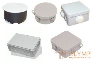
Therefore, in the catalogs of stores you can often find electrical products called “junction box”, “junction box”, “distribution box”, “junction box” and you might think that these are different groups of goods, although in fact there is no difference between these names , that is, all terms will mean the products depicted in the picture:
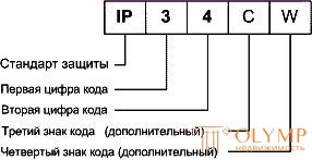
Differently named junction boxes differ in other ways:

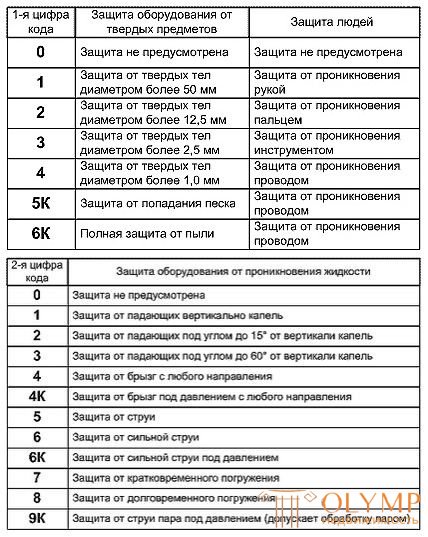
Protection Levels Table
These signs are often interrelated, below are a few examples:
Protection Levels Table
There is one important rule concerning all types - access to the connection points of wires for inspection, maintenance, modification and repair should always be provided.
As is well known, conductor metal has fluidity - the property to deform under pressure with a loss of elasticity, due to which the terminal clamp loses its mechanical strength, therefore its electrical conductivity deteriorates.
Under such circumstances, the place of contact is heated under heavy loads, which leads to thermal expansion and further deterioration of the strength characteristics - such a contact starts to spark, the contact surfaces burn, the destruction processes become avalanche-like and the connection fails.
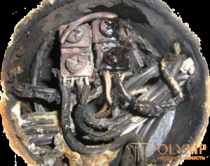
Burnt wiring
Therefore, the clamps must be regularly tightened. Even if Wago terminal blocks are used that do not require maintenance, you still should not bury the lid tightly - the lion's share of breakdowns in the wiring falls on the junction boxes.
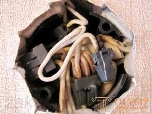
Another option with VAGO
Fans of aesthetics in this case can be advised to use removable elements of the decor for masking the lid immediately, than to invent something, lamenting about damaged wallpaper, if something burns out in the box.
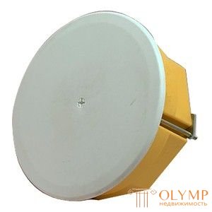
As a rule, distribution boxes for wiring of the latent type have the form of the cylinder. This is due to the fact that it is easier to drill a cylindrical blind hole in the wall with a drill and a special drill bit than to gouge a rectangular niche in the wall material.

hidden junction box
Therefore, these boxes have standardized sizes, and accordingly, they are commercially available drills for these diameters. The most common size is 60 mm. This is due to the fact that the most popular installation box for switches and sockets (socket) also has these dimensions, which allows you to use one drill when installing them.
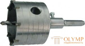
crown 60 mm
But often these sizes are simply not enough to accommodate all the wires and their connections, therefore, split boxes of large diameters are used: 70, 80, 100 mm.

installation of distribution box
For external wiring, the junction box is made both cylindrical and rectangular.
But rectangular is more convenient - it turns out more free space to connect the wires, it is possible to install terminal blocks or several rows of distribution buses, you can install several parallel inputs on the sides of the box.
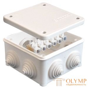
Junction box with terminal strip
The box for external electrical wiring is often operated in adverse climatic conditions, so it is necessary to seal the inner space so that the conductors are not exposed to the corrosive effects of moisture and dust, and that it is completely unacceptable - to ingress of water inside.
The tightness of the box determines its IP protection degree (ingress protection - penetration protection). The first letter means protection from dust and solid objects, the second - from moisture and liquids.
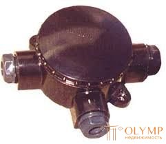
The appearance of the sealed junction box, designed to work in explosive conditions:

Obvious is the dependence of the material of the junction box on its purpose and tightness - for working in especially dangerous and corrosive environments, thick-walled stainless steel is used, for open wiring plastic walls to provide the necessary impact resistance.
Distribution boxes for concealed wiring are the cheapest in terms of cost - all mechanical and protective functions are performed by the wall. The purpose of the box also determines its internal structure, for example, the UK-2P box with built-in connection terminals is used to branch lines of wired radio.

Photo_УК2П
A similar system, but already for disconnection of power wires is used in the box for external wiring:
 The mounting and wiring box of the hidden type wiring for drywall has special presser feet, pressed against the reverse surface of the drywall, thereby fixing the cylinder in the hole.
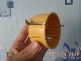
drywall junction box with special presser feet
When installing open wiring on the floor use floor junction boxes:

If the wiring is under the floor, then use special boxes, equipped with sealed covers or hatches

distribution box with hatches
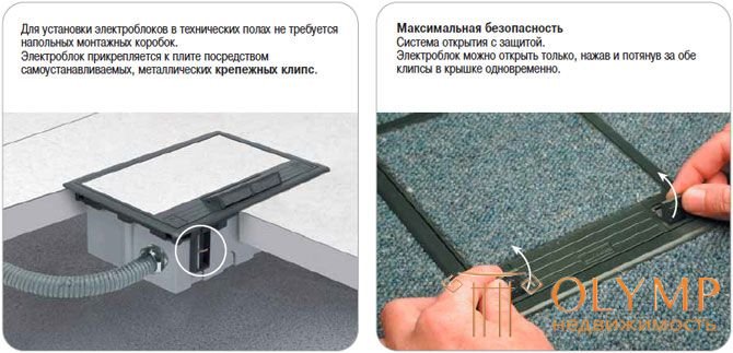
Floor junction boxes can also have built-in sockets:
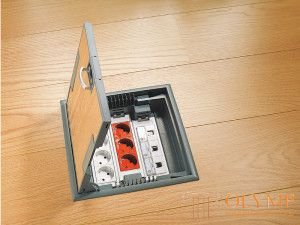
electrical distribution box with sockets
For hidden wiring in wooden houses use exclusively metal boxes.
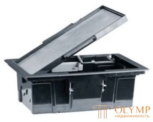
Metal shredded boxes
For various monitoring and control systems, boxes with built-in low-voltage low-current terminal blocks are used:
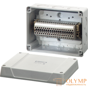
For work in switching systems of three-phase load boxes with multiple terminals are used.
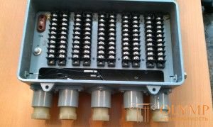
For the distribution of three-phase voltage it is more appropriate to use several parallel buses in the box:

Different junction boxes have their own ways of sealing the contact connections of wires - depending on the degree of IP, a variety of gaskets and seals are used, from ordinary rubber, cut with a knife in the right place to the required diameter, to completely waterproof, clamped with special couplings.
In order to install any junction box presented above with your own hands, you need to study the appropriate instructions, in which the manufacturer must describe in detail all the characteristics and nuances of installation.
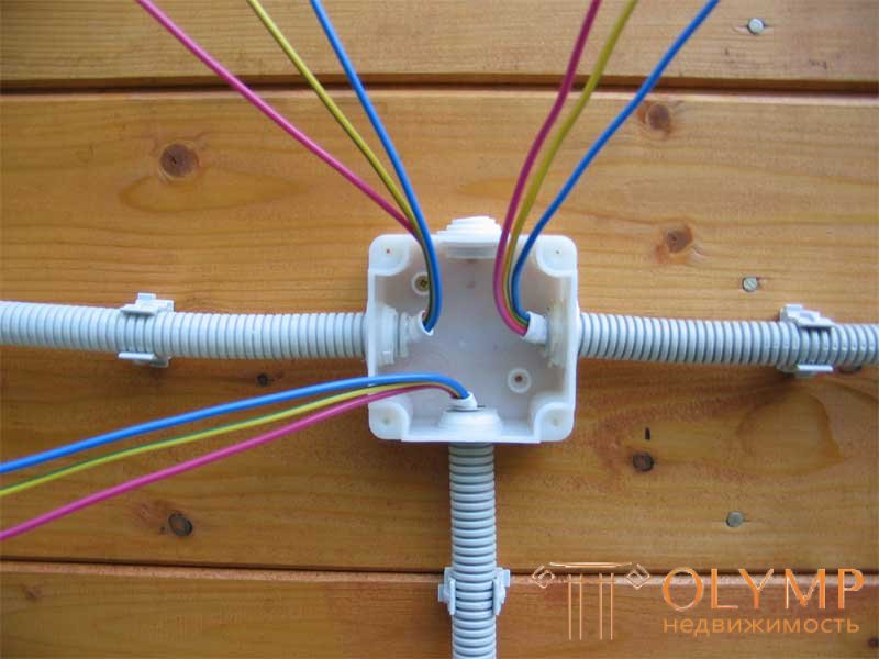
We perform connections in the junction box
The correct connection of wires in the junction box is in many ways the key to the reliability of your electrical network. Indeed, unlike the connections in the switchboard, switchboards or, as they are also called, the junction boxes are more closed for service and the contact connections here are much more difficult to check. That is why, even at the stage of installation, their quality and accuracy should be given maximum attention.
Before connecting the wires in the junction box we advise you to study the rules of their installation. After all, it is important not only to connect the wires to each other qualitatively, but also to correctly bring them into the junction box, as well as conveniently arrange them for possible inspection or repair.
First of all, let's consider the rules applicable to the arrangement and installation of wiring in the distribution network. After all, it is with this factor begins any installation. 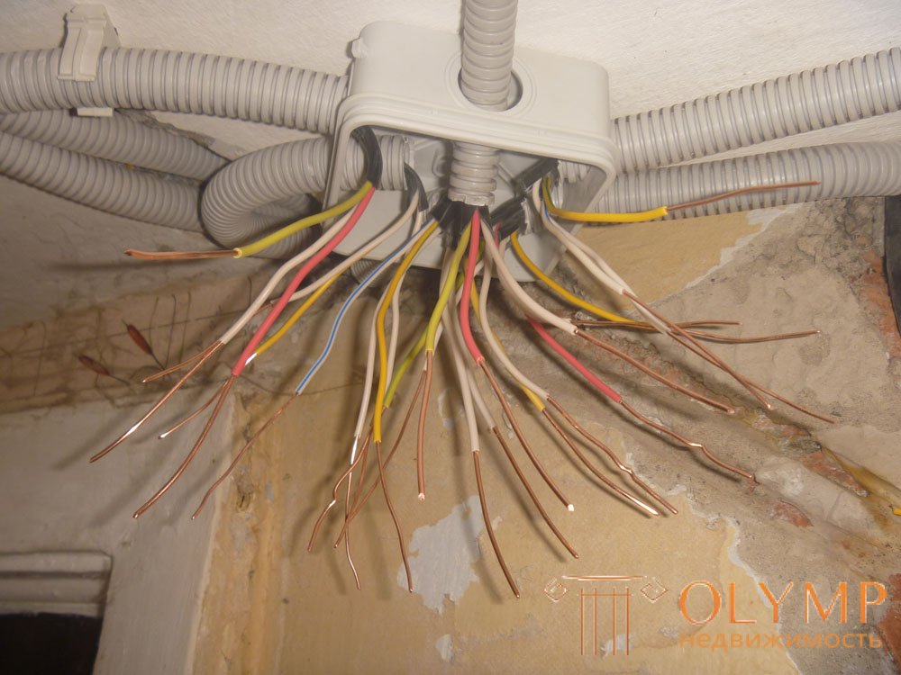
Wiring Rates in Junction Box
So:
First of all, let's look at how to connect the wires in the junction box. After all, contact connections are often the most vulnerable point of any electrical network and any flaws manifest themselves very quickly.
According to clause 2.1.21 of the electrical installation code, all connections of wires and cables should be made by welding, soldering, crimping, screw or bolt clamp. Other connection methods, especially for twisting, are not allowed. Based on this, let's consider each of the possible connection methods separately.
So:
Welding of wires in the junction box is performed using a special welding transformer and a carbon electrode. The cost of such products is large enough for easy replacement of wiring in the apartment, so you can often find homemade devices. Usually it is transformers up to 600 W and voltage 9 - 36V.
Soldering wires in the junction box is carried out using conventional technology and does not impose special requirements. The only point worth paying attention to is the quality of such compounds. Indeed, in the case of heating, the tin will quickly heat up and the contact will disappear. In order to prevent this from soldering, they are often combined with a twisting method.
Note! Screw terminals should be clamped single-core wire. If you use stranded copper wire, then you need to purchase special lugs that will not allow the screws to break off the stranded wire strands when clamping. These tips are attached to the wire by crimping.
Having an idea of the methods of connection, we can talk about how to properly connect the wires in the junction box. At home, you will need knowledge of how to connect an outlet and a switch. But first, let's look at the scheme of the junction box itself.
The junction box is designed to connect electrical receivers to the supply wire. It is usually located at the entrance to the room above the switch. The switch should be located at the entrance to the room from the side of the door handle.

The photo shows the connection option of the final junction box.
Note! Если в вашей сети освещения разные группы запитаны от разных фаз трехфазной сети, то фазный провод должен иметь окраску, соответствующую фазе трехфазной сети. То есть фаза А должна иметь окраску желтого цвета, фаза В – зеленого и фаза С – красного цвета.
Теперь переходим к вопросу как соединить провода в распределительной коробке для подключения одной, двух и более розеток. Для этого нам понадобится трехжильный провод с сечением соответствующим суммарной нагрузке всех розеток.
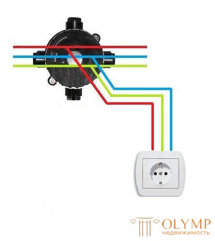
Подключение в проходной распределительной коробке розетки
So:
А вот распайка проводов в коробке для подключения выключателя несколько сложнее и зависит от количества контактов выключателя. Так для одноклавишного выключателя проводов должно быть два, для двухклавишного – три, а для трехклавишного – четыре.
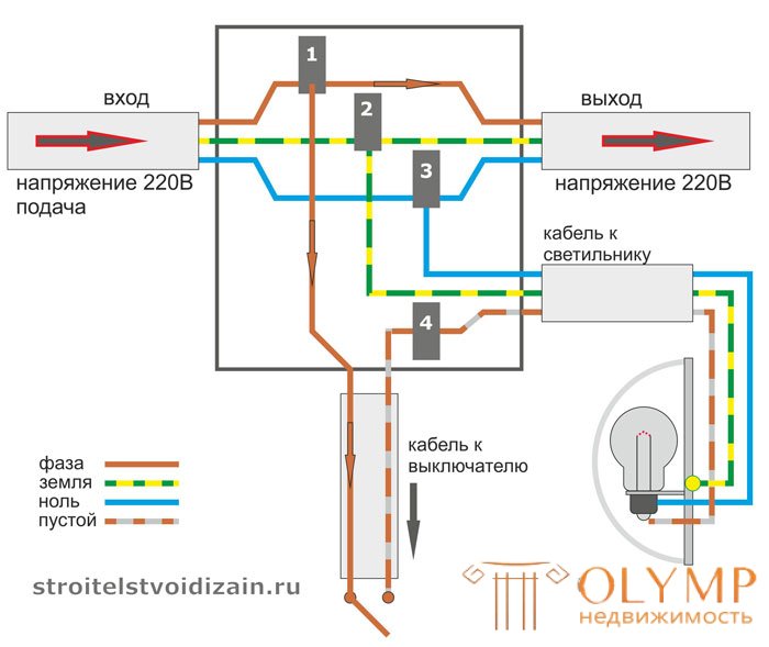
Подключение выключателя в распределительной коробке
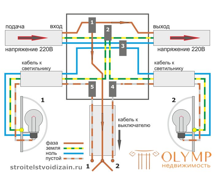
Подключение двухклавишного выключателя в распределительной коробке
Conclusion
Как и электрическая распределительная коробка соединение проводов на любых других участках должно отвечать высоким требованиям. Поэтому не стоит пренебрегать нормами ПУЭ к данному вопросу. Ведь лучше выполнить качественное соединение еще на этапе монтажа, чем потом искать проблему в уже действующей электрической сет

Выполняем подключения в распределительной коробке
Правильное соединение проводов в распределительной коробке во многом является залогом надежности вашей электросети. Ведь в отличие от соединений в распределительном щите распределительные или как их еще называют распаячные коробки более закрыты для обслуживания и контактные соединения здесь значительно сложнее проверить. Именно поэтому еще на этапе монтажа их качеству и правильности следует уделить максимальное внимание.
Перед тем как соединять провода в распределительной коробке советуем вам изучить правила их монтажа. Ведь важно не только качественно соединить провода между собой, но и правильно завести их в распределительную коробку, а также удобно расположить для возможного осмотра или ремонта.
Прежде всего давайте рассмотрим правила, предъявляемые к обустройству и монтажу проводки в распределительной сети. Ведь именно с этого фактора начинается любой монтаж.

Нормы монтажа проводки в распределительной коробке
So:
Прежде всего давайте рассмотрим способы соединения проводов в распределительной коробке. Ведь именно контактные соединения зачастую являются наиболее уязвимым местом любой электрической сети и любые недоработки проявляются очень быстро.
Согласно п.2.1.21 ПУЭ все соединения проводов и кабелей должны производится сваркой, пайкой, опрессовкой, винтовым или болтовым сжимом. Другие методы соединения, особенно это касается скрутки, не допускаются. Исходя из этого давайте рассмотрим каждый из возможных методов соединения по отдельности.
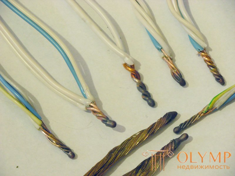
Соединение методом сварки
So:
It is not necessary to use a welding electrode and a carbon electrode. You can often find homemade devices. Usually it is transformers up to 600 W and voltage 9 - 36V.
Solder wire connection
Soldering wires in the junction box is carried out using conventional technology and does not impose special requirements. The only point worth paying attention to is the quality of such compounds. Indeed, in the case of heating, the tin will quickly heat up and the contact will disappear. In order to prevent this from soldering, they are often combined with a twisting method.
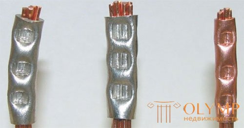
Wire connection crimping method
Note! Screw terminals should be clamped single-core wire. If you use stranded copper wire, then you need to purchase special lugs that will not allow the screws to break off the stranded wire strands when clamping. These tips are attached to the wire by crimping.
Having an idea of the methods of connection, we can talk about how to properly connect the wires in the junction box. At home, you will need knowledge of how to connect an outlet and a switch. But first, let's look at the scheme of the junction box itself.
The junction box is designed to connect electrical receivers to the supply wire. It is usually located at the entrance to the room above the switch. The switch should be located at the entrance to the room from the side of the door handle.

The photo shows the connection option of the final junction box.
Note! If in your lighting network different groups are powered from different phases of a three-phase network, then the phase wire must have a color corresponding to the phase of a three-phase network. That is, phase A should have a yellow color, phase B should be green and phase C should be red.
Now we come to the question of how to connect the wires in the junction box for connecting one, two or more outlets. To do this, we need a three-core wire with a cross section corresponding to the total load of all sockets.

Connection in the distribution box of the socket
So:
But the wiring of wires in the box for connecting the switch is somewhat more complicated and depends on the number of contacts of the switch. So for the one-button switch wires should be two, for the two-keyboard - three, and for the three-keyboard - four.

Connection of a switch in a junction box

Connecting a two-button switch in a junction box
This is a universal box, which, thanks to a well-thought-out construction, allows installation in solid walls and in facade insulation systems. A big advantage is the ability to adjust the installation depth of the box on demand of a particular installation.
The offer of these boxes is supplemented by the possibility of using two covers, the first main and the second with the possibility of opening without the use of tools. The hinged cover is equipped with a spring and a lock. The hinged cover series includes a mounting plate that allows installation of classic instruments. In case of their installation in insulated facades, the devices are safely hidden under the hinged lid. The covers installed in the boxes provide IP 30 protection, but after applying a suitable additional seal, IP 44 protection is achieved.
KUZ boxes can also be used as wiring junction boxes; for this option, S-KSK 2 terminal boxes are provided, as a box for installing electrical devices or lightning conductor terminals or other customer solutions.
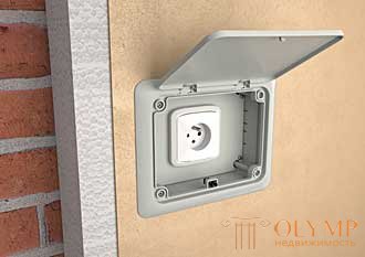
Due to the wide range of applications, KUZ boxes are divided into four configurations:
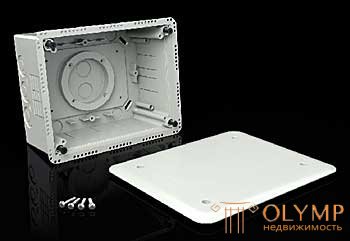
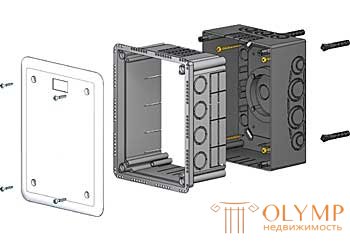
KUZ box kit with lid V 180.
The kit is intended for installation in solid walls or direct installation in insulation materials for building facade insulation.
The box has the ability to adjust the installation depth from 85 to 140 mm.
Material: PC ABS, self-extinguishing, halogen-free
Size: box 196x156x85-140 mm, cover 210x170 mm
cover 210x170 mm
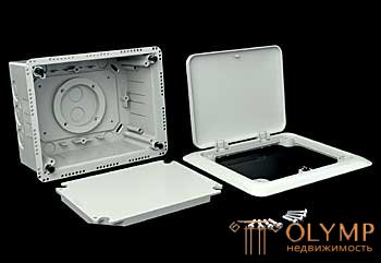

The solution of the KUZ-VO variant is such as the KUZ-V, only the box is equipped with a VO 180 hinged lid, which allows opening without the use of tools.
The interior of the box is available for installation and classic devices that will be hidden under the surface of the wall.
The kit includes a mounting plate that allows the installation of various devices.
Material: PC ABS, self-extinguishing, halogen-free
Size: box 196x156x85-140 mm, cover 210x170 mm
cover 210x170 mm
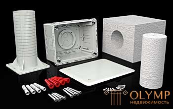

The set under the designation KUZ-VI is designed for installation in facade insulation systems. The box is identical with KUZ-V, only supplemented by a carrying pipe, external and internal insulation, fixing material for fastening the pipe to the wall and self-tapping screws for fastening the box to the pipe.
The kit allows use in insulated facades with a minimum thickness of 120 mm. The maximum thickness of insulation is 300 mm. The advantage of this option is that the bottom of the box is insulated from the base, which limits the occurrence of thermal bridges.
Material: PC ABS, self-extinguishing, halogen-free
Size: box 196x156x85-140 mm, cover 210x170 mm
cover 210x170 mm
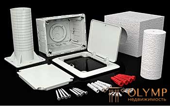
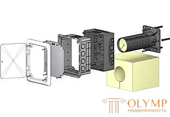
The KUZ-VOI kit as well as the KUZ-VI kit is intended for installation in facade thermal insulation systems, it only contains a hinged cover VO-180.
The kit is designed to install devices that will be installed under the surfaces of the facade. Also suitable as KUZ-VI for classic devices, switches, sockets, three-phase sockets or also for example. to hide the output of the garden hose.
Material: PC ABS, self-extinguishing, halogen-free
Size: box 196x156x85-140 mm, cover 210x170 mm
cover 210x170 mm
Kez
Wiring boxes used in building facade insulation
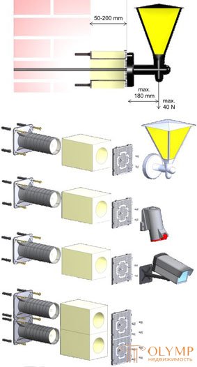
Designed for installation of devices (sockets, switches) on the thermal materials for thermal insulation of building facades. Due to its design, the emergence of thermal bridges is prevented. The use of a KEZ box allows you to install electrical appliances with an insulation thickness of 50 to 200 mm.
The set includes dowels, screws, bolts, holders for fixing the box and instruments.
The box must be installed devices with appropriate protection (IP) from the environment. 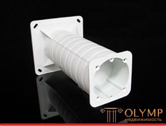
Size: 120 x 120 x 200 mm
Material: self-extinguishing halogen-free PP
Temperature stability: from -25 to +60 ° С
Package includes:
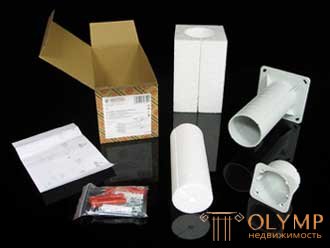
User's manual:
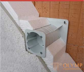
1. Before installation it is necessary to reduce the length depending on the thickness of the insulation layer of the facade of the building.
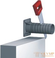
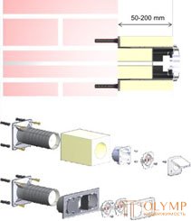
2. KEZ, KEZ-3 - Wiring boxes used for thermal insulation of buildings
The supporting structure is attached to the wall with screws and dowels, depending on the type of material.
A cable is pulled through the supporting structure and shorted insulation is inserted.
With the help of 4 screws (included), the box in which the necessary devices are installed is attached to the structure.

Wiring boxes used in building facade insulation
Type -3 allows installation of instruments in multi-site frames with a thickness of insulation from 100 to 250 mm.
Size: 120x120x250 mm
Mounting plate used for thermal insulation of building facades
It is intended for installation of electrical appliances (outdoor lighting, motion sensors, power sockets up to 400V, etc.) on the warmed walls of building facades. Due to its design prevents the emergence of thermal bridges.
Not intended for installation of satellite dishes and other bulky structures. The use of a mounting panel allows you to install equipment with an insulation thickness of 50 to 200 mm.
The area for installation of equipment is 120x120 mm. The set includes dowels, screws, bolts, holders for fixing the box and instruments.
Individual MDZ can be interconnected, which allows, if necessary, to increase the area of the installation field. 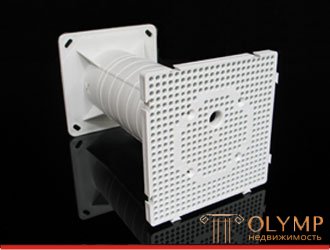
Size: 120 x 120 x 200 mm
Material: self-extinguishing halogen-free PP
Temperature stability: from -25 to +60 ° С
Load: max. 4 kg
Package includes:

User's manual:
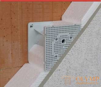
1. Before installation it is necessary to reduce the length depending on the thickness of the insulation layer of the facade of the building.

2. MDZ - Mounting plate used for thermal insulation of building facades
The supporting structure is attached to the wall with screws and dowels, depending on the type of material.
A cable is pulled through the supporting structure and shorted insulation is inserted.
With the help of 4 screws (included), the box in which the necessary devices are installed is attached to the structure.

As with the electrical junction box, the connection of wires in any other areas must meet high requirements. Therefore, you should not neglect the rules of OLC to this issue. After all, it is better to perform a high-quality connection at the installation stage than to look for a problem in an already existing electrical network.
Что бы оставить комментарий войдите
Комментарии (0)