"ELECTRICAL DEVICE RULES"
-7th edition.
APPROVED BY the Ministry of Energy of the Russian Federation, order of July 8, 2002 N 204.
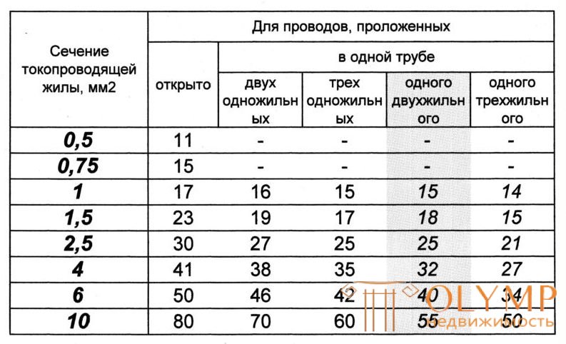
1.3.10. The permissible continuous currents for wires with rubber or PVC insulation, cords with rubber insulation and cables with rubber or plastic insulation in lead, PVC and rubber sheaths are given in Table. They are taken for temperatures: lived +65, ambient air +25 and earth + 15 ° С.
When determining the number of wires laid in a single pipe (or a multicore conductor core), the zero working conductor of a four-wire system of three-phase current, as well as grounding and neutral protective conductors are not taken into account.
The data contained in the table. Should be applied regardless of the number of pipes and the place of their laying (in the air, floors, foundations).
Allowable continuous currents for wires and cables laid in boxes, as well as in trays in bunches, should be accepted as for cables laid in the air. When the number of simultaneously loaded wires is more than four, laid in pipes, ducts, and also in trays in bunches, the currents for the wires should be taken according to the table. as for wires laid open (in the air), with the introduction of reducing coefficients of 0.68 for 5 and 6; 0.63 for 7-9 and 0.6 for 10-12 conductors.
Permissible continuous current for wires with rubber and polyvinyl chloride insulation with copper conductors, A
Selection of automatic protection.
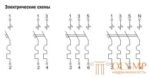
Circuit breakers are designed to protect against overload and short-circuit currents of electrical circuits with single and group consumers of electrical energy, i.e. to protect the wiring from overload, and not to protect end-use consumers, as many think.
It would seem that - 20A is written - it means that if the current consumption flowing through this machine is exceeded, at least half an ampere, the “switch” should “turn off” ...
In fact, everything is not so simple ...
According to GOST R 50345—2010 and the international standard IEC 60898-1: 2003 (edition 1.2) Circuit breakers have three types of tripping characteristics from instantaneous tripping current (minimum current value that causes automatic tripping of the circuit breaker without intentional delay) and various applications:
- household circuits made of aluminum wires, - characteristic B;
- household circuits made of copper wires, - characteristics B or C;
- production loads with electric motors and control gears of fluorescent lamps - characteristics C or D.
The tripping characteristic of the circuit breakers should provide effective circuit protection without tripping at rated current In.
This time-current characteristic (tripping characteristic) of the circuit breaker is determined by the conditions and values according to the tables: 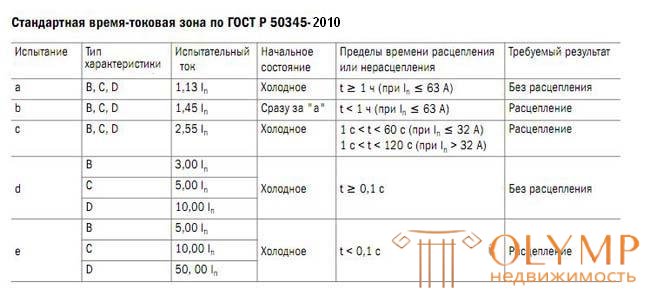
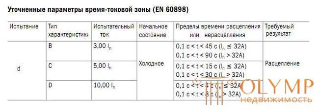
The parameters of the standard time-current zone are set for a reference calibration temperature of 30 ° C.
For the standard time-current zone, the following conditional parameters are set:
- conditional non-tripping current (conventional non-tripping current) - the set current value that the switch is able to conduct for the conditional time without tripping: Int = 1.13 In , where In is the rated current indicated on the label;
- conventional tripping current (conventional tripping current) - the set value of the current, causing the circuit breaker tripping within the conventional time: It = 1.45 In ;
- instantaneous tripping current (instantaneous tripping current) - the minimum current value that causes the automatic opening of the circuit breaker without intentional time delay;
- conditional time equal to 1 hour for switches with rated current up to and including 63 A and 2 hours with rated current above 63 A;
Timeout trip characteristics: 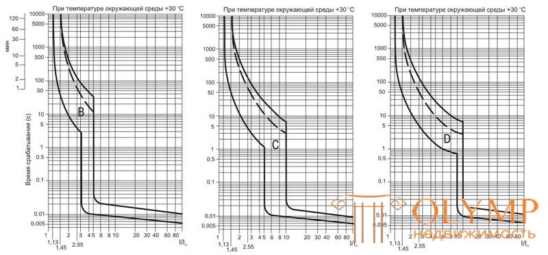
In the figures, the dotted line is the upper limit of the time-current characteristic for circuit breakers with a rated current In ≤ 32 A.
In addition to the time-current characteristics, the trip current also depends on the ambient temperature and the number of circuit breakers placed side by side (on a single DIN rail).
The dependence of the load factor (Kt) and (Kn) of the switch on the ambient temperature and the number of machines located next to each other: 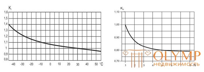
The non-tripping current for the circuit-breakers placed next to each other, depending on their number (n) and the ambient air temperature, is determined by the formula: I = 1.13 • In • Kn • Kt ,
where In is the rated current at a temperature setting of the thermal releases of 30 ° C (indicated on the marking);
Kn is the load factor depending on the number of automata;
Kt - load factor depending on the ambient temperature. 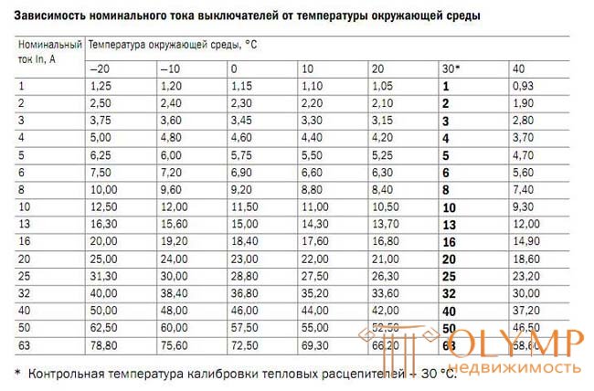
From all of the above, it follows that a circuit breaker with a response characteristic C at room temperature (18-20 ° C) has Kt = 1.05 and, respectively:
- Int = 1.19 In (23.8A for a 20A automatic machine) keeps uncoupling a virtually unlimited amount of time (where In is the rated current indicated on the label at a temperature setting of the thermal release of 30 ° C);
- It = 1.52 In (30.4A for the 20A automaton) holds up to the 1st hour;
- 2.68 In (53.6A for 20A automatic machine) up to 2 minutes;
and only when the load current is exceeded by more than 3 - 5 times, the response occurs in less than a second ...
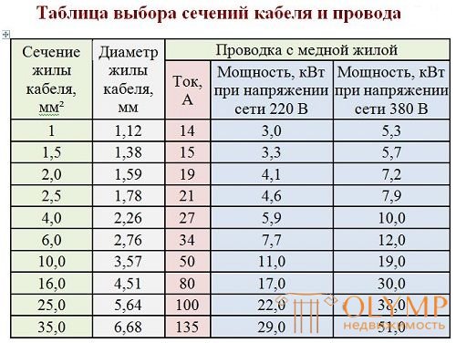
When installing apartment electrical wiring, copper wires with a cross section of 1.5 mm, 2.5 mm, 4.0 mm are used.
Quite often, a group circuit is connected to one machine, with the subsequent division of several individual consumption circuits in the switchboard, and the wiring cross-section of the secondary circuits is not always equal to the primary one.
Therefore, it is necessary to select the protection circuit breaker for the group circuit with the condition that it can protect the secondary circuit with the smallest section, i.e.
copper core cross section (mm.) | ||||
1.5 | 2.5 | 4.0 | 6.0 | |
Permissible continuous current according to PUE-7 (A) | nineteen | 27 | 38 | 46 |
Recommended automatic protection | ten | sixteen | 25 | 32 |
Conditional noncoupling current at 30 ° С Int = 1.13 In (A) | 11.3 | 18.08 | 28.25 | 36,16 |
Conditional noncoupling current at 18 ° С Kt = 1.05 Int = 1.19 In (A) | 11.9 | 19.0 | 29.7 | 38.0 |
Conditional tripping current at 30 ° С It = 1.45 In (A) | 14.5 | 23.2 | 36.25 | 46.4 |
Conditional tripping current at 18 ° С Kt = 1.05 It = 1.52 In (A) | 15.2 | 24.4 | 38.1 | 48.7 |
The most preferred when laying internal (especially hidden) wiring is a cable NUM.
NYM cable.
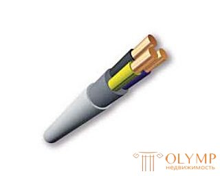
NYM cable is designed for industrial and domestic fixed installation of power supply (open and hidden) indoors and outdoors. Outdoor use is possible only outside direct exposure to sunlight. It is possible to use the cable over plaster, in it and under it in dry, wet and wet rooms, as well as in masonry and concrete, with the exception of direct fitting in vibrating and stamped concrete. Laying can be carried out in pipes, in closed installation and curved channels.
NYM wire construction.
Vein - single-wire copper conductor;
Insulation - polyvinyl chloride (PVC) plastic compound with a distinctive color.
Intermediate casing - melnapolnennaya rubber;
The outer shell is a non-burning polyvinyl chloride plasticate of light gray color.
The NYM cable uses an intermediate rubber sheath that:
- allows you to easily and conveniently "cut" the cable during installation;
- increases the fire safety of the cable;
- increases cable flexibility.
Table of diameter and wire section |
Content:
In electrical networks there are many parameters defined in various ways. Among them there is a special table, the diameter and cross-section of the wire with its help are determined with high accuracy. Such accurate data is required when adding an electrical load, and the old wire is not labeled. However, even the legend does not always correspond to reality. This is mainly due to the dishonesty of manufacturers of products. Therefore, it is best to make independent calculations. The use of measuring devicesTo determine the diameter of the conductors of wires and cables are widely used various measuring devices, showing the most accurate results. Mainly for these purposes the use of micrometers and calipers is practiced. Despite the high efficiency, a significant disadvantage of these devices is their high cost, which is of great importance if the tool is planned to be used only 1-2 times.
As a rule, special devices are used by professional electricians who are constantly engaged in electrical installation work. With the right approach, it becomes possible to measure the diameter of the conductors even on work lines. After obtaining the necessary data, it remains only to use a special formula: Defining a cross section with a rulerAn economical and accurate method is to determine the cross-section of cables and wires using an ordinary ruler. In addition, you will need a simple pencil and the wire itself. To do this, the core wire is stripped of insulation, and then tightly wound on a pencil. After that, the total winding length is measured with a ruler.
The obtained measurement result must be divided by the number of turns. The result is the diameter of the wire, which is needed for further calculations. The cable section is determined by the previous formula. To obtain more accurate results, the wound coils should be as large as possible, but not less than 15. The coils are tightly pressed between each other, since the free space contributes to a significant increase in error in the calculations. To reduce the error, you can use a large number of measurements made in different versions. A significant disadvantage of this method is the ability to measure only relatively thin conductors. This is due to the difficulties that arise when twisting a thick cable. In addition, it is required to purchase a product sample in advance to perform preliminary measurements. Table of ratios of diameters and sectionsDetermining the cross sections of cables and wires using formulas is considered to be a rather laborious and complicated process that does not guarantee an accurate result. For these purposes, there is a special ready-made table, the diameter and cross-section of the wire in which their ratio visually represents. For example, with a conductor diameter of 0.8 mm, its cross section will be 0.5 mm. A diameter of 1 mm corresponds to a cross section of 0.75 mm, and so on. It is enough to measure the diameter of the wire, and then look at the table and calculate the desired cross section.
When performing calculations you need to follow certain recommendations. To determine the cross-section, it is necessary to use a wire that is completely insulated. This is due to the possible reduced size of the cores and the higher insulating layer. In case of any doubts in cable dimensions, it is recommended to purchase a conductor with a higher cross section and power reserve. In the case of determining the cross section of a multicore cable, the diameters of the individual wires are first calculated, the values obtained are summed up and used in the formula or in the table. |
Что бы оставить комментарий войдите
Комментарии (0)