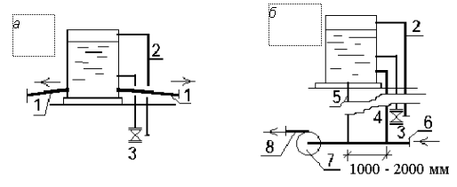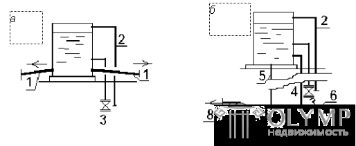
Expansion vessels are installed in the building when connected to the heating network using an independent (closed) scheme (see Fig. 2.3) or heating from a local boiler house. The installation diagrams of the expansion vessels are shown in fig. 2.7, 2.8, 3.10. They protect the heating system from an increase in pressure: designed to contain excess water during its temperature expansion. Constant exchange of water in the tank is ensured by circulation - the tank is connected to the return pipe of the heating system by two pipes (connecting and circulation) at two points with different pressures, the distance between these points should be 1-2 m. displayed in the room duty staff.
 | Fig. 3.10. Installation schemes of expansion vessels: a - in the system with natural circulation; b - in the system with a circulation pump; 1 - highways; 2 - overflow pipe; 3 - control tube; 4 , 5 - circulation and connecting pipelines; 6 - from the heating system; 7 - pump; 8 - in a water heater |
Install the expansion vessels in the highest point of the system (in the attic, the technical floor) and insulated. In systems with top wiring and natural circulation, these tanks are usually placed near the center of the building and connected directly to the supply pipe of the heating system. Pipeline slopes are assigned in such a way that air released from the water is easily removed through the tank. In systems with lower wiring, the expansion vessel is connected to the return pipe of the heating system in the basement by special risers.
The volume of the vessel is determined by the formula
Vback = 0.0465Vsist , (3.18)
where Vsist is the volume of water in the heating system, which is about 20 liters per 1000 W of thermal power of the system when using cast-iron radiators.
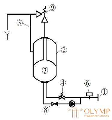
 | In modern heating systems of individual buildings, automatic expansion systems that perform the same functions as a conventional expansion vessel, but are located directly in a heating unit, have proven themselves well. The scheme of such an EDER Elko Mat installation is shown in Figure 3.11. Fig. 3.11. EDER Elko Mat automatic expansion system layout: 1 - heating system return line; 2 - expansion tank; 3 - elastic chamber for water; 4 - valve; 5 - air exhaust line; 6 - pressure sensor; 7 - pump; 8 - check valve; 9 - safety valve |
When overheating and expansion of water in a closed heating system 1 increases the pressure. The valve 4 opens, and the excess water from the heating system 1 flows into the elastic chamber 3 , which in turn displaces the air from the space between the tank body 2 and the elastic chamber through the air line 5 into the atmosphere.
When water is cooled and due to a decrease in its volume in the heating system, pressure decreases. The signal of the pressure sensor 6 starts the pump 7 , which raises the pressure in the system by supplying water from the tank to it until it reaches the pressure setting level on the valve.
The EDER Elko Mat installations are available in 3 sizes with an expansion volume of 200, 300, and 500 liters. With additional tanks, the working volume can be increased to 1,500 liters.
The required amount of expansion for such an installation corresponds to Vbak and is determined by the formula (3.18).
Что бы оставить комментарий войдите
Комментарии (0)