Typically, apartments are powered by single or three phase external networks. Here, as they say, as anyone lucky. Of course, three-phase networks, as a rule, provide the possibility of obtaining a greater load.
The most subtle question - the organization of grounding and zeroing. We are all accustomed to the fact that in sockets and plugs (single-phase networks) we have 3 contacts: phase, zero and earth. It is very good if all these three wires come to your house (with single-phase connection), or 5 wires with three-phase (3 wires of 3 phases, zero and ground).
It’s harder when you have 2 wires with a single phase or 4 wires with a three phase connection. In this case, if one grounding / grounding wire comes to you (the so-called PEN, you can isolate PE from it (ie grounding) and N (that is, neutral or neutral wire).
Of course it will be somewhat conditional, but safe enough. And if you equip your dashboard with special RCD devices (protective cutout device), then you can consider yourself safe. The protective shutdown devices (RCD) react to non-standard leakage currents resulting from direct or indirect contact of a person with current-carrying parts, violation of integrity or ignition of the wiring . RCD first of all saves the person a life and protects the equipment from ignition.
more about RCD 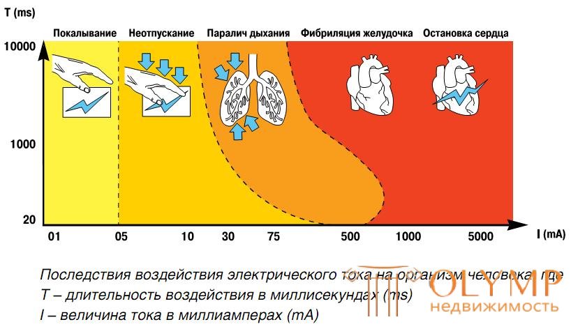
The general recommendation is as follows. At the entrance of the cottage or apartment should be the so-called "fire UZO" with a current of 100 or 300 mA. It is designed to turn off the network in case of fire, which is very important for wooden houses. It is not recommended to install RCDs with 30mA current at the input - there will be permanent trips.
So, through the RCD of 300 mA, we tie up the entire electrical network in the house. But, through the UZO 30 mA or 10 mA, we connect those consumers where leaks are possible. First of all, these are rooms associated with water (bathroom, toilet, kitchen, boiler room, pumping station, etc.). It does not hurt to put all the sockets on the RCD - it won't be worse. But there is no sense in bringing lighting to the RCD, the probability of electric shock is small, on the contrary, it can only get worse. Imagine, on a dark evening, you have an RCD in the kitchen. If this also turns off the light, it will only aggravate the situation.
Pay attention to the fact that, in contrast to automata, neutral wires also close on the RCD. But the most important thing is that the neutral wires coming out of different RCDs cannot be connected together - these RCDs will work, signaling a leak.
So how does our RCD. Very simple. It is a current transformer: two windings, the current entering the RCD flows through one, and the current passing through the load through the second, i.e. coming out. 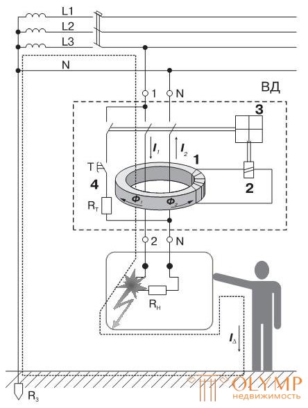
If everything is normal and there is no leakage current "on the side" on the load, then the incoming and outgoing currents are equal and the RCD operates normally. If a leak occurs (for example, the zero cable is shorted to the body of the washing machine, and you touch it), then a part of the current will go through your body and the RCD will instantly work.
Connection diagrams to a three-phase, single-phase network.
On the Internet you can find dozens of house connection diagrams.
Here are three of the most successful options for connecting to a three-phase network: two options for the separate supply of PE and N, and one option for the combined supply of PEN (the cheapest and therefore the most common option). The procedure for connecting to a single-phase network is similar.
Schemes of switchboards 3f network.
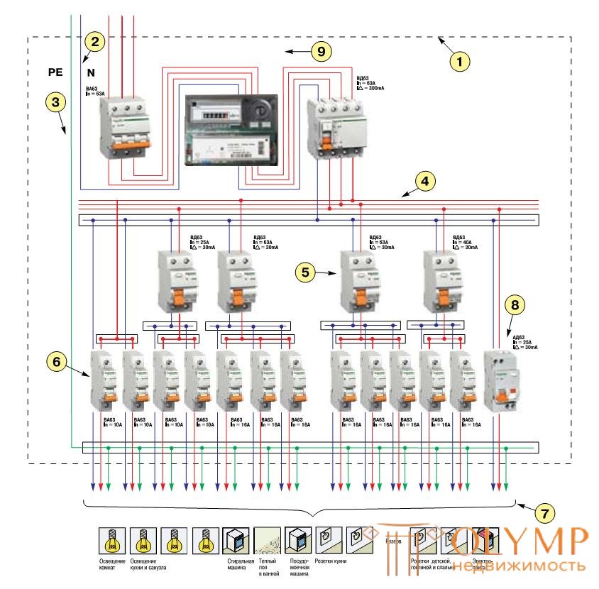
Option 1. The scheme of the group distribution board of the cottage (PE and N are separate)
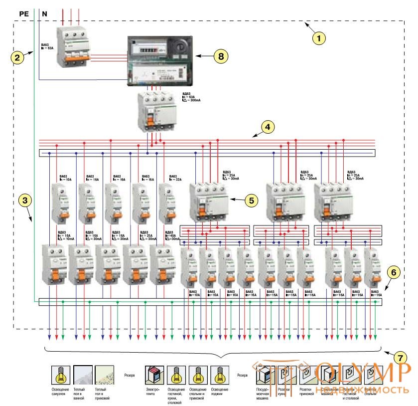
In the diagram below, all groups are protected by an RCD with a sensitivity of at least 30 mA.
Electrical equipment of bathrooms, wet rooms, where the leakage current is most dangerous, is protected by a RCD with a tripping differential current of 10 mA to ensure complete safety.
1 - Plastic or metal body shield.
2 - Connecting elements of zero working conductors.
3 - Connecting element of PE clamps of a conductor, as well as a potential equalization conductor.
4 - Connecting element of phase conductors of group circuits.
5 - Differential Current Switch.
6 - Circuit Breakers.
7 - Group chain lines.
8 - Counter.
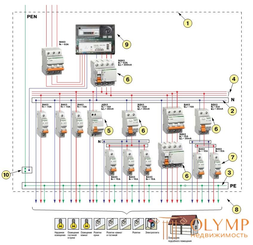
Option 2. Scheme of a group switchboard of an individual building (house or cottage) - (PE and N are separate)
In the diagram above, all the main devices are divided into separate groups. Differential protection devices with a sensitivity of 30 mA designed to protect people are installed on all major consumer groups, except for lighting rooms where human contact with live parts is unlikely, and the air conditioning system, which must be additionally grounded.
1 - Plastic or metal body shield.
2 - Connecting elements of zero working conductors.
3 - Connecting element PE conductor and potential equalization conductor.
4 - Connecting element of phase conductors of group networks.
5 - Differential Current Switch.
6 - Circuit Breakers.
7 - Group chain lines.
8 - Differential circuit breaker.
9 - Counter.
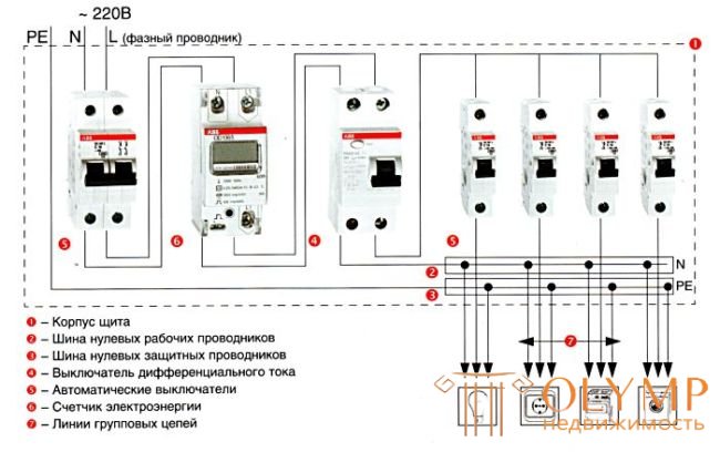
Option 3. Scheme of a group switchboard for an individual dwelling house (PEN: i.e. PE and N are combined)
An RCD with a differential current of 300 mA is installed at the input to the cottage (when installing a RCD with a lower leakage current, false alarms are possible due to the large length of electrical wiring and the high natural background of electrical equipment leakage). The first three circuit breakers are designed to protect the lighting circuits against overload, short circuit and leakage currents. A group of RCDs and three circuit breakers is designed to protect sockets. Three-phase circuit breaker and RCD protect powerful consumers (for example, electric stove). The last line, consisting of one RCD and two circuit breakers is designed to protect the circuits of a separate building (for example, utility room).
1 - Plastic housing shield.
2 - Connecting element of zero working conductors.
3 - The connecting element of the terminals of the zero working conductors, as well as the potential equalization conductor.
4 - Connecting element of input terminals of protective devices of group circuits.
5 - Differential current circuit breaker.
6 - Differential current switch.
7 - Circuit Breakers.
8 - Group chain lines.
9 - Counter.
Schemes of switchboards 1f network.
Option 1. Panel distribution panel layout (PE and N are separate)
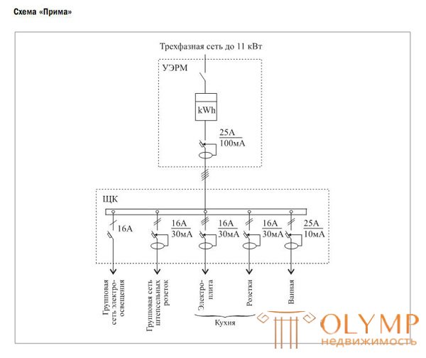
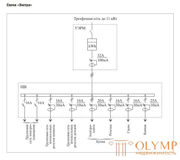
Moscow city construction standards MGSN 3.01-01 "Residential buildings"
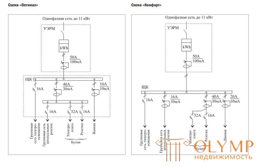
Electric power supply scheme for apartments of the II category of comfort:
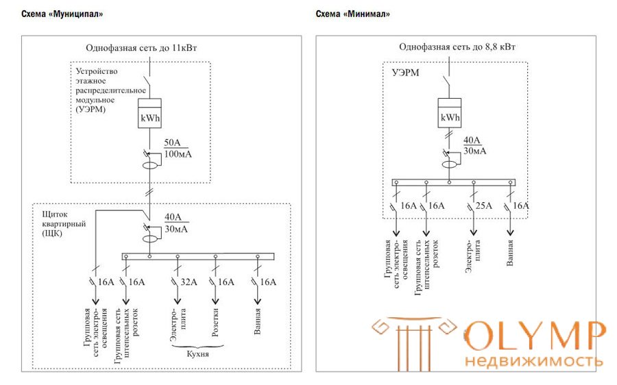

Electric power supply scheme for apartments of the I category of comfort:
Что бы оставить комментарий войдите
Комментарии (0)