There is no uniform, unified classification of terminal blocks in the scientific literature, but in the professional community there are several categories of classification:
Relief (with a relief clip)
With wire protection (tear protection)
For attachment to the surface
Cable mate
very fine
low current
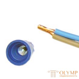
Quite simply done with the use of special caps. With their use, the connection is more reliably insulated, contact is better. The outer part of such a cap is molded from plastic that does not support combustion, and a metal threaded conical part is inserted inside. This insert provides a large contact surface, improving the electrical characteristics of the connection. This is a great way to connect two (or more) wires without soldering.
Twisting wires with caps is even easier: insulation is removed by 2 cm, the wires are twisted slightly. They are put on the cap, with the effort of turning several times, until the metal is inside the cap. All connection is ready.
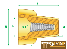
Connecting insulating clips (PPE) are used for electrical work, in order to isolate, connect and fix into a single “bundle” of wires and cables. Connecting insulating clips connect and fix the copper wires in a twist. Made of galvanized steel spring, nylon body, not containing halogens. Refractory. The conical shape of the spring provides a secure grip and hold twist the wires throughout the life of the. The case completely isolates the twist. The clamp is screwed onto the previously stripped and joined together ends of the wires. Additional tools are not required, there is the possibility of reuse. Temperature range: from -10 ° C to + 75 ° C.
The connecting isolating cap, is used for fast connection, isolation of several wires. Installation takes place on bare wires, by screwing in, without the participation of any special tool.
- Wings greatly simplify the installation of wires of large sections.
- Wide clamp base provides protection and complete insulation of the connection.
- The spring has a special square profile that creates a thread directly on the twist and securely holds the connected wires.
- The contact spring is longer than the standard budget PPE.
Contact part: galvanized steel spring
Body Material: PVC
Temperature range: -10 ° C to + 75 ° C
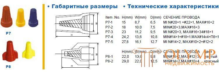
Body color coding makes it easy to choose the right size
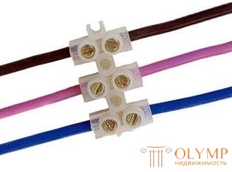
Connecting screw terminals are designed to connect the wires to each other. This is the most common type of terminal strip. Usually used for switching wires in junction boxes. Material: polyethylene, polyamide, polycarbonate, polypropylene. If you work with aluminum wires, then these terminal blocks are better not to use - they are strongly deformed in screw terminal blocks and can be broken.
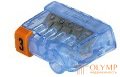
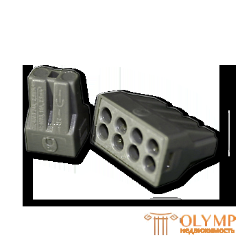
Self-tightening terminal blocks can have from 2 to 8 places for wires with a minimum cross section of 0.75 mm2 and maximum - 2.5 mm2. Able to withstand loads up to 4-5 kW (24 A). Such clamping terminals are very easy to install, greatly reducing its time - no need to twist and then isolate the wires. But, they occupy more space in the junction boxes, in contrast to the twist, which can be given any shape, laid, bending it as you like.
Terminals are special wiring accessories that are designed to quickly and safely connect wires.
A conductor without insulation must be inserted into the hole in the terminal and the lever must be lowered. Such a connection / branch is always reliable - the conductors are not damaged, the quality of the connection does not depend on the skills of the person who deals with them. Separately, it is worth noting a useful order in the system - each conductor has a separate terminal “socket”, which guarantees safety in the junction box.
Two types are mainly used:
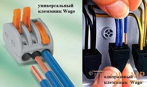
Vago Terminal Blocks
The peculiarity of these terminal blocks is that they can only be operated at low currents: up to 24 A with a cross-section of copper wire of 1.5 mm, and up to 32 A with a cross-section of 2.5 mm. When connecting loads with high current consumption, the connection of wires in the junction box must be done in another way.
The mounting and mounting terminals of KBM (quick mounting terminals) TDM are used for connecting and branching single-core copper and aluminum wires or multi-core copper wires with a lug in AC electrical circuits with voltage up to 380V with a frequency of 50 Hz.
When using the construction and assembly terminals of KBM, the installation of wires is carried out without the use of tools.
The presence in the terminals of the contact paste provides the ability to simultaneously connect aluminum and copper wires
The most popular method among folk craftsmen, but the most unreliable. It is not recommended by PUE for use, as it does not provide adequate contact, which can lead to overheating and the occurrence of a fire. This method can be used as a temporary one, for example, to check the operability of the assembled circuit, with a mandatory subsequent replacement with a more reliable one.
Correct twisting electrical wires
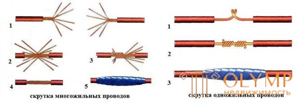
Even if the connection is temporary, you must do everything by the rules. The methods of twisting stranded and single-conductor conductors are similar, but have some differences.
When twisting stranded wires, the procedure is as follows:
Connecting the wires in the junction box with a single core with the help of twist easier. Cleared from isolation conductors intersect and twist their fingers along the entire length. Then take the tool (pliers and pliers, for example). In one, the conductors are clamped near the insulation, the second is stranded by the conductors, increasing the number of turns. The junction is insulated.
Soldering or welding significantly increases the installation time, this procedure is much longer than with the use of terminal blocks - you need to remove the insulation from the wires, strip each wire, if it is soldering, connect the welder, then isolate all the wires. If necessary, rewire the wires (for example, add a wire), there are also difficulties - remove insulation, solder again (boil). With terminal blocks everything is much easier. but better contact is achieved using welding or soldering.
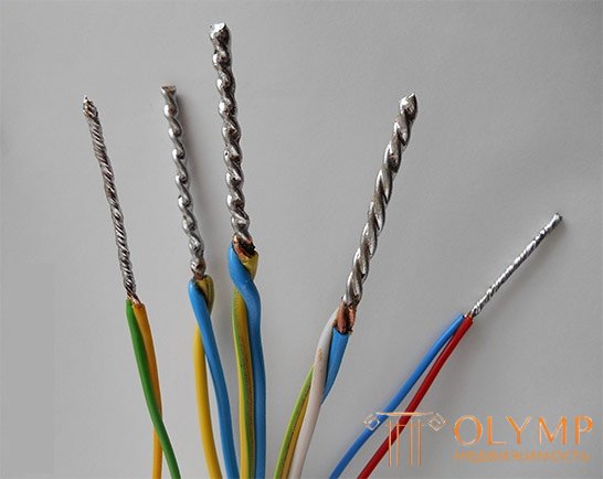
The most reliable is the connection of wires by welding . It has the smallest contact resistances, as a result, increased heating is practically absent. In addition, over time, such a connection does not lose its properties.

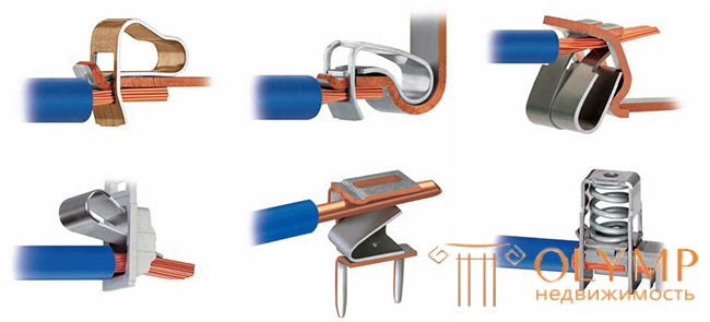
Crimping wires has recently become increasingly popular.
After all, a large number of fairly cheap tools for crimping wires appeared on the market, and the price of consumables for this method is quite low.
To perform this type of connection, a mechanical tool is used to crimp tips or sleeve sleeves of insulated connecting; or a tip in insulated forks; or tips ring isolated
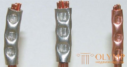
Wire connection crimping method
| m sp connection |
Value of resistance (for DC test) measurement without repetitions (single sampling) worst case error |
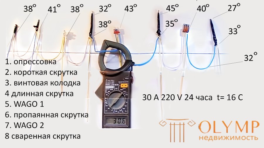
Heating temperature (contact base) during passage AC 30 A 220 V 50 Hz for 1 day at a temperature of supplying conductors of 32 tarsus Celsius (indoors 16 ° C) |
| Long twist not soldered | 302 |
41 short, 45-35 long |
| VAGO WAGO spring clip | 458 | 43-40 |
| Screw pad | 40 | 38 |
| Connecting insulating clip | 68 | |
|
KBM mounting and mounting terminals (quick mounting terminals) TDM |
645 | |
| wire connection crimping | 38 | |
| soldering twist | 32-38 | |
| twist welding | 33-27 |
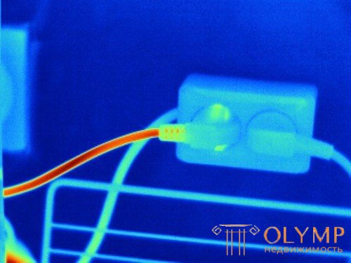
Thermal control of electrical equipment is one of the priorities for the prevention of fires in electrical installations . Thermal imaging control is provided for TCP 181-2009 (02230) RULES OF TECHNICAL OPERATION OF USER ELECTRICAL INSTALLATIONS. With its help, defects are detected at an early stage of development, thereby excluding cases of emergency shutdown of equipment, and troubleshooting is performed in a planned manner.
How is a thermal imaging survey of power supply systems ? An electric current flowing through a conductor or dielectric creates a certain amount of energy or heat and changes its temperature field. The temperature change can be recorded during thermal imaging of electrical equipment with a thermal imager.
Thermal imaging inspection of power supply systems is a method that has a low cost compared to traditional survey methods, which allows you to quickly and remotely, without stopping the equipment at an early stage, to detect faults in the operation of the power supply system.
Thermal control of electrical equipment and power supply systems is used throughout the chain from the production and distribution of energy, transporting it along power lines to substations, at the substations of regional and local electric networks, and finally, at switchgears and electrical switchboards of final consumers.
The final consumer of electricity cannot predict possible failures in the operation of the power supply system, as a rule, they relate to random phenomena, but with a periodic thermal imaging survey of electrical distribution devices, a pre-emergency condition of electrical contacts can be detected. An increase in the temperature of contact groups can be caused by:
Knowing about a possible defect, the end user can take steps to eliminate it promptly and eliminate a possible accident.
Thermovision monitoring of electrical switchgear means long-term monitoring of temperature fields in electrical switchboards in order to identify contacts and areas of electrical wiring that have an elevated temperature. According to the degree of heating of a particular area, one can judge whether the electrical wiring, electrical device or electrical contact is in good order, and the need for mandatory preventive measures can be assessed.
To ensure the reliability of the power supply system, thermal imaging monitoring is desirable to carry out at least twice a year, during periods of increased electricity consumption, and this is the summer and winter periods. In the summer, the increase in electricity consumption occurs mainly due to the use of air conditioners, and in the winter period due to the inclusion of electric heaters in the work. Electrical consumption of the enterprise changes during the day, and this must also be taken into account when conducting thermal imaging monitoring.
Thermal monitoring, due to the high efficiency of the results and low cost of work, can be recommended both to the heads of energy departments and to individuals who are interested in trouble-free operation of real estate objects:
Conditions for conducting a thermal imaging survey of power supply systems.
Thermal imaging of internal power supply systems can be conducted year-round, but it is necessary to read the load at the time of the measurements, as well as environmental conditions such as ambient temperature, humidity, etc. При обследовании внутренних электрораспределительных устройств надо исключать температурное воздействие отопительных приборов, которые должны быть экранированы алюминиевой фольгой или другими теплоотражающими материалами.
Тепловизионное обследование наружных систем электроснабжения может проводиться круглогодично, но при условии отсутствия дождя, снегопада и тумана, кроме того, следует учитывать влияние скорости и направления ветра.
Обследуемые наружные поверхности не должны подвергаться длительному воздействию прямого и отраженного солнечного облучения в течение не менее 3 часов до проведения работ по тепловизионному контролю и непосредственно в процессе измерения.
Целью работ по тепловизионному обследованию системы электроснабжения и электротехнического оборудования является выявление дефектов и неисправностей по одному из следующих возможных параметров:
Как показывает опыт, избыточная температура, при действующей нагрузке в 40-50% от максимальной, измеренная непосредственно в месте неисправности в зависимости от опасности неисправности может быть разделена на три степени:
избыточная температура <5°С.
Обнаруженное появляющееся горячее пятно следует держать под контролем и принять меры к устранению дефекта во время проведения запланированного по графику технического обслуживания;
excess temperature 5-30 ° C.
Frolic hot spot. Take as soon as possible measures to eliminate the identified defect, taking into account the operating conditions of the installation.
excess temperature> 30 ° C
Emergency hot spot. Take immediate steps to eliminate the identified defect, taking into account the operating conditions of the installation.
Examples of thermograms survey of electrical equipment.
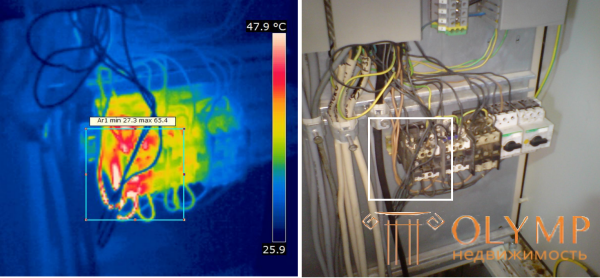
Overheating relay

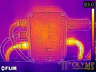
Overheated junction box power cord
Что бы оставить комментарий войдите
Комментарии (0)