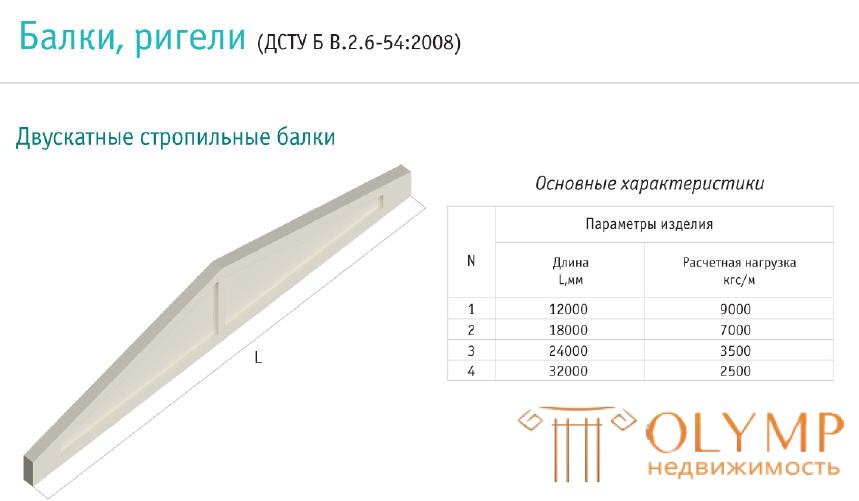

Beams of this type are used to cover buildings with a span of 6 to 18 m with a pitch of 6 m. They are used in buildings with and without lanterns, with overhead cranes or overhead vehicles. They are intended for areas with different snow loads and for rooms with non-aggressive, slightly aggressive and highly aggressive environments. In the latter case, the thickness of the protective layer increases. The slope of the top flange of the beams is 1:12, and with a low-slope roof 1:30. Beams at the supports have fortifications, and at the points where the shelf adjoins the grid, they are tufts. In buildings with a span of 6 and 9 m with a non-aggressive medium, T-beam beams with non-stressed reinforcement are used from a package of rods of a periodic profile of class A-11, welded together in separate places along the length of the package. The wall and the shelf are reinforced with welded frames. The longitudinal bars of the frames are made of steel grade A-11, the transverse ones are made of steel grade A-1. Pre-stressed I-beams are used for spans of 12-18 m. They are used in coatings of buildings with highly aggressive environment, subject to an increase in the protective layer of concrete and the presence of anti-corrosion coating. The wall and the upper shelf along the length of the beam are reinforced with three welded frameworks - middle and extreme Cr-1 and Cr-2, the lower one - with clamps and rods. The longitudinal bars of the frames are made of steel of a periodic profile of class A-111, the transverse ones of cold-drawn wire of class B-1, or bars of steel of the class A-111. Possible options for prestressing reinforcement: rod periodic profile of steel grade A-IY, A-Y, At-Y, At-YI; high-strength wire with a diameter of 5mm class B-11, BP-11; reinforcing ropes with a diameter of 15 mm class K-7. The joints are reinforced along the perimeter of the widening to the entire height of the beam with clamps made of cold-drawn wire of class B-1. To limit the width of the opening of cracks when tempering pre-stressed reinforcement, they are also reinforced with welded meshes С-1 of class B-1 wire, located perpendicular to the pre-stressed reinforcement. In the upper shelf for fixing the cover plates after 1.5 and 3 m along the length of the beam, embedded parts MN-2 and Mn-3 are placed. The beams are attached to the columns with anchors and welding of embedded parts Mn-1. Beams are calculated as free-lying on two supports. Loads - permanent and temporary (snow). Loads from the walls of the lantern, overhead transport and snow bags in places of elevation changes are taken as a concentrated force. Efforts in the beam sections are determined by the methods of building mechanics. When the slope of the roof is 1:12, the calculated bending moment is a section located at a distance of 0.37L from the support, and with a slope of 1:30 - in the middle of the span. The calculation for the two groups of limiting states is performed for the stage of operation, manufacture, installation and transportation of the beam.
Что бы оставить комментарий войдите
Комментарии (0)