9.1. Trigonometric leveling
Trigonometric leveling - determining the excess between points using an inclined sighting beam (Fig. 73).
At the point A set theodolite, at the point B - rail. A tape measure or a rod measures the height of the theodolite. Using the vertical circle of the theodolite, determine the angle of inclination of the sighting axis of the pipe ν when it is aimed at any point of the rail. The distance from this point to the heel of the staff is called the height of sight l . The length of the line AB is measured with a tape or range finder.
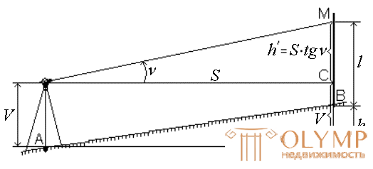
Fig. 73. Trigonometric leveling.
From pic. 73 we have:
h + l = h΄ + V ,
h = h΄ + V - l ,
because h΄ = S ∙ tgν,
that
h = S ∙ tgν + V - l .
If the telescope is directed on the rail to the theodolite height, then V = l and the excess is calculated by the formula
h = S ∙ tgν .
If the distance was measured with a tape, then the horizontal distance of the line AB is S = D ∙ cosν .
Trigonometric leveling becomes very productive when distances are measured by a range finder.
In the case of using the thread range finder S = D ∙ cos 2 ν , then
 .
.
The theodolite, equipped with a vertical circle and thread rangefinder is called a total station , and a set of geodetic measurements to determine the planned and altitudinal position of points is called a total station.
9.2. Determination of the excess of trigonometric leveling, taking into account the correction for the curvature of the Earth and refraction
In the previous section, when determining the height difference between two points by trigonometric leveling, it was assumed that the distance between these points is small and the plumb lines passing through points A and B can be considered parallel, and the sighting beam is a straight line. In fact, at distances greater than 300 m, corrections for the curvature of the Earth K and refraction r (Fig. 74) must be taken into account.
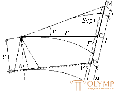
Fig. 74. Trigonometric leveling, taking into account corrections for the curvature of the Earth and refraction.
S ∙ tgν + V + K = h + l + r ,
h = S ∙ tgν + V - l + K - r ,
 ,
,
h = S ∙ tgν + V - l + f .
If the telescope is directed on the rail to the theodolite height, then V = l and the excess is calculated by the formula
h = S ∙ tgν + f .
Corrections for the curvature of the Earth and refraction f = K - r are taken into account only at distances AB more than 300 m.
9.3. Tacheometric survey, its purpose and devices
Tacheometric survey is a combined survey, in the process of which the planned and altitudinal position of the points is simultaneously determined, which makes it possible to immediately obtain a topographical plan of the area.
Tacheometry literally means quick measurement or quick measurement.
The position of the points is determined relative to the points of the shooting justification: planned - by the polar method, high-altitude - by trigonometric leveling. The lengths of the polar distances and the density of the picket (rack) points (the maximum distance between them) are regulated in the instruction for topographic and geodetic works.
In the production of a tacheometric survey using a geodetic instrument tacheometer , designed to measure horizontal and vertical angles, lengths of lines and elevations. The theodolite, having a vertical circle, a device for measuring distances and a compass for orientation of the limb, refers to theodolites - tacheometers .
Theodolites - tacheometers are most technical accuracy theodolites, for example T30.
For tacheometric surveys, tacheometers with nomogram definitions of elevations and horizontal lines are also used. Currently widely used electronic tachometers.
9.4. Production of tacheometric survey
Tacheometric survey is performed from the points of filming, they are called stations . Most often, theodolite-high-altitude passages are used as a shooting justification.
Characteristic points of the situation and terrain are called rack points or pickets . Rack points on the ground do not fix.
To determine the planned position of the points of the survey network, horizontal angles and lengths of the sides are measured. The lengths are measured with measuring tapes or steel tape measures in the forward and reverse directions with an accuracy of 1: 2000.
The heights of the points are determined by trigonometric leveling. Tilt angles are measured at two positions of the vertical circle in the forward and reverse directions. The difference in elevations is allowed no more than 4 cm for every 100 meters distance.
Work at the station when the tacheometric survey is performed as follows.
The theodolite is placed in a working position above the travel point (the instrument is centered and leveled), the instrument height is measured V , it is marked on the rail and recorded in the log.
When the circle right " P " direct the telescope on the rail mounted on the adjacent (back or front) point of the course, and take a readout on a vertical circle. Then the pipe is transferred through the zenith and the limb is oriented on the side of the turn, i.e. on a horizontal circle set the countdown 0 °, fix the alidade and, rotating the dial, direct the telescope to the rail. Then take a reading on the vertical circle when the circle is left " L " and calculate the place of zero ( MO ) of the vertical circle. Samples and value MO are recorded in the log.
After the indicated actions, the survey of details (characteristic points of the situation and relief) at the station is started, all measurements are recorded in the aerial logbook.
At each station, simultaneously with the filling of the journal, an outline is drawn up - a schematic drawing on which the positions of the railing points with their numbers are drawn, the outlines of the terrain are drawn, the skeleton of the relief is indicated, and grounds are signed (Fig. 75).
The skeleton of the relief is depicted in the form of lines connecting the points between which a flat slope on the ground, i.e. no kinks. Arrows indicate the direction of the slope. Well-defined relief forms are sometimes shown on the outline by conditional horizontals. The outlines of the situation and the objects to be removed are indicated by conventional signs or inscriptions.
Sometimes the outline is drawn before the start of shooting and then they are shooting in accordance with the outline.
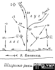
Fig. 75. Outline tacheometric survey.
On rack points set rail. When the circle is left “ L ” and oriented limb, rotating the alidade, they consistently guide the telescope to the lath points, make readings on the ranging yarns, horizontal and vertical circles and record them in a journal. The middle stroke of the grid of the filaments of the telescope is induced to the height of the device, marked on the rail. If the height of the device on the rail is not visible due to interference, it is suggested to any readout on the rail (most often multiple to meters or half meters, for example: 2, 2.5 m or 3 m). The height of sight l is recorded in the log.
After the end of the survey at the station, the telescope is again guided to the point of travel along which the theodolite is oriented, and take a readout on a horizontal circle. The discrepancy between 0 ° and the taken reading is allowed no more than ± 5 '.
Rack points should cover the shooting area evenly. The distances from the station to the rack points and the distance between the rack points should not exceed the tolerances specified in the instruction for the total station survey.
Processing the results of the tacheometric survey includes the following work:
1. Calculation of the coordinates and elevations of the points of tacheometric moves;
2. Calculation of elevation of the point points;
3. Construction of the tacheometric survey plan.
9.5. Electronic Total Stations
The electronic total station combines a theodolite, a light-range meter and a microcomputer, allows you to perform angular and linear measurements and to carry out joint processing of the results of these measurements.
Tacheometers, in which all devices (goniometric, distance measuring, telescope, keyboard, processor) are combined into one mechanism, are called integrated tacheometers.
Tacheometers, which consist of a separately constructed theodolite (electronic or optical) and a distance meter, are called modular tacheometers.
To perform a survey, an electronic total station is installed at the station and set up in accordance with the measurement conditions. On pickets put special landmarks with reflectors, when pointing to which the distance, horizontal and vertical angles are automatically determined. If the total station has a non-reflective mode, then measurements can be made on lath points in which it is not possible to install a pole with a reflector. Microcomputer tachometer on the results of measurements calculates the coordinate increments and the excess of h, taking into account all amendments. All data obtained during measurements are stored in a special storage device (information storage). They can be transferred using an interface cable on a PC, where using a special program, the final processing of measurement results is performed to build a digital terrain model or topographic plan. The combined use of an electronic total station with a PC allows you to fully automate the process of building a terrain model.
Currently, electronic tachometers of foreign firms Sokkia (Fig. 90), Topcon, Leica, and Trimble are most widely used. They have built-in software for the production of virtually the entire spectrum of geodetic works: the development of geodetic networks; shooting and carrying out in nature; solving problems of coordinate geometry (direct and inverse geodesic problems, calculating areas, calculating serifs). Angular accuracy of such devices can be from 1 "to 5", depending on the accuracy class.
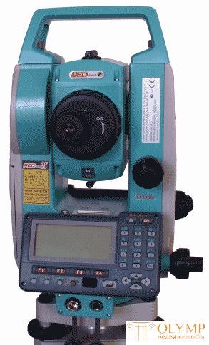
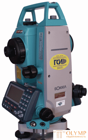
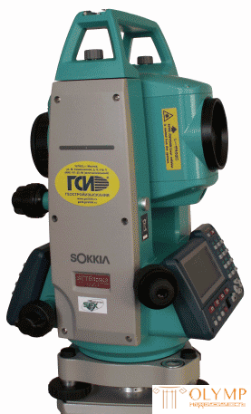
Fig. 90. Electronic total station Sokkia SET 530RK3
The latest electronic total stations are robotic total stations equipped with a servo drive.
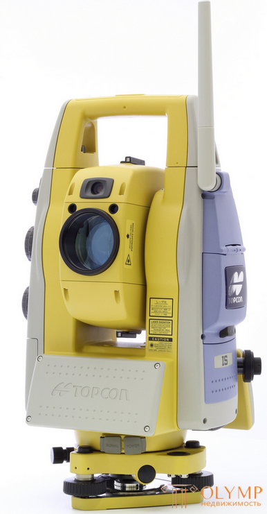
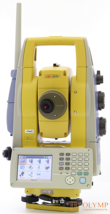
Fig. 91. Topcon IS-305 robotic total station
These devices can independently be guided by a special active reflector and make measurements. A robotic total station with a servo drive can be additionally equipped with a special radio control system, and then only one person can take a picture. Such a scheme of shooting increases the productivity of shooting work by about 80%.
9.6. Questions for self-control
1. What is the essence of trigonometric leveling?
2. What are the features of creating a theodolite-altitude course as a justification for shooting?
3. What instruments are used in the tacheometric survey?
4. What is the work at the station during the tacheometric survey?
5. What are the peculiarities of automated tacheometric survey?
Что бы оставить комментарий войдите
Комментарии (0)