General information about traction . Traction is a profiled strip, made of mortar (plaster) mortar with templates using translational rectilinear or curvilinear motion. Traction draw interior and facades - cornices, belts, platbands, sockets, ellipses, columns, arches, caissons.
Traction made from different solutions: lime, lime-gypsum, cement, cement-lime (mixed) and decorative, where the aggregates are coarse marble or stone chips. Extrusion of cement and decorative mortars is more laborious due to the rigidity of the solutions, which are also applied in thin layers, making wide throws.
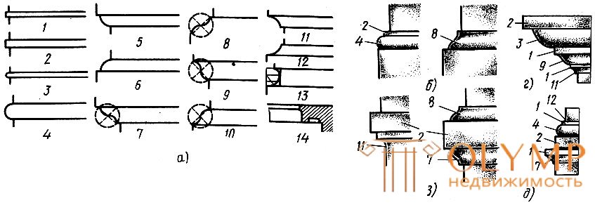
The draft consists of one or several architectural breakages (Fig. 59, a – e), differing in profile (cross section) into straight and curvilinear. From a combination of simple break-ups, complex break-ups are obtained, for example, astragalus, which is a roller with a shelf.

Fig. 59. Architectural breakup (a) and profiles (bd): straight: 1 - shelf, 2 - shelf; curvilinear: 3 - roller, 4 - shaft, 5, 6 - quarter shaft (direct and reverse), 7.8 - heel (direct and reverse), 9, 10 - jib (direct and reverse), 11, 12 - fillet ( direct and inverse), 13 - scotia, 14 - teardrop 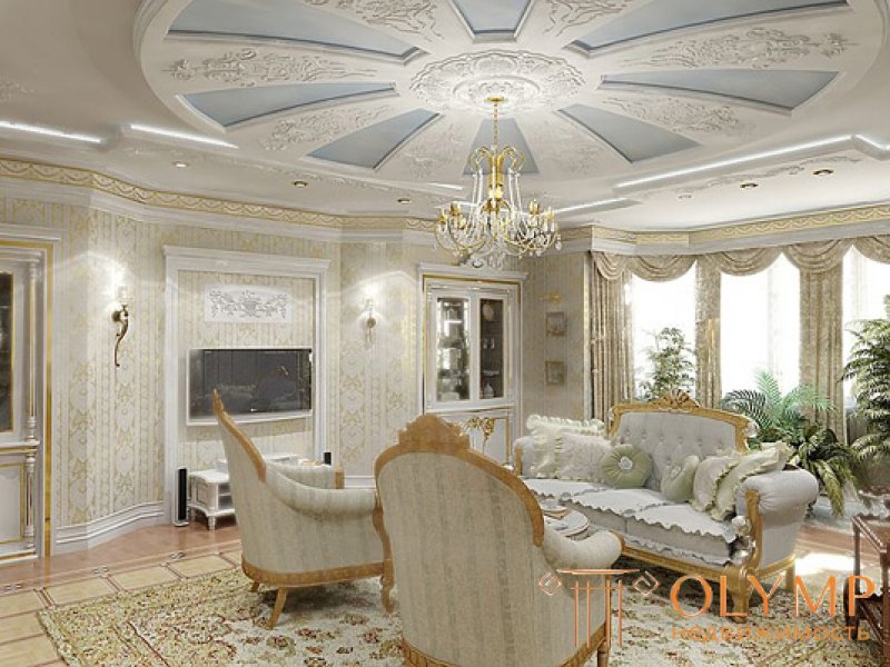
From different bummer architects design rods, curtain rods, belts, platbands. Most of the work done using templates. Sometimes only quarter slices (padugs) are drawn from the hand.
Execution padug . Padugs are pulled out with ordinary or shaped treads (Fig.60, a-b). Conventional poluterki apply length from 750 to 1000 mm, but with a narrow blade. Before making the padugi, they plaster the ceiling and the top of the walls. The ceiling is rubbed or smoothed, the walls can be made only in the ground. Then prepare a creamy solution, put it in the husks formed by the ceiling and walls. After each application of the solution, it is given with the help of a trowel the desired shape in the form of a quarter of a circle. This operation is repeated several times until the padug is completely formed. After that, it is straightened, trimmed or rubbed with a trowel 250-300 mm long. The padugu made in rough is covered with the solution filtered through a frequent sieve, using small shading. They also erase the surface, moving the trowel along the length of the paduga or across, i.e. along the curve.
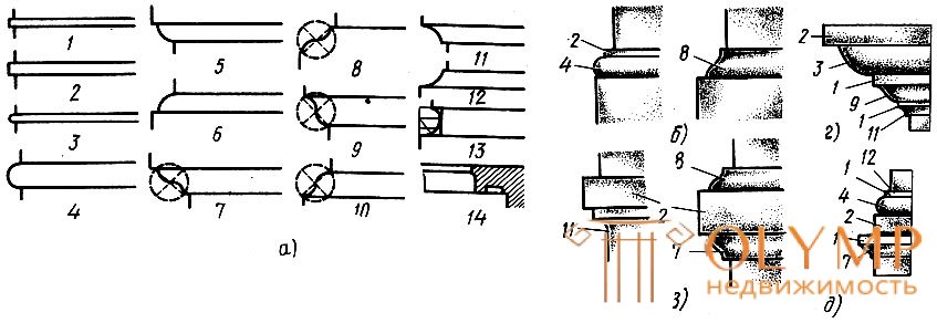
Fig. 60. Padugi device by hand: a - an ordinary scraper, b - a shaped scraper, in - stretching a padugi; 1 - a rule, 2 - a sled, 3 - poluterok
When performing the paduga with a shaped trowel, first put the solution in the husks and give the padug its shape with the usual trowel. Then, a shaped one is put into a padug made in rough, pressure is made on it and guided along the length of the padug or moved across it. The ends, upholstered in roofing steel, cutters cut off the excess mortar, giving the padug the correct shape. If shells form on the padug, they are smeared with a solution and after that they are once again carried out with a shaped trowel along the paduga. The scoop is applied, leveled and rubbed with a small scraper.
The most accurate padugu is obtained in the following way. A rule 10-15 cm wide is hung on the wall. A sled is nailed to the shaped floor scraper, i.e. a board of the same width as the width of the rule that was hung, or somewhat wider than it. This is necessary in order for the tangers to be kept strictly in one position, pressing the sled to the rule. The solution is applied in the usual way in several stages and for each applied layer, including the covering layer, drawn with a scraper.
Making templates . The shape of the template (Fig. 61, a) depends on the thrust for which it is made. The template consists (Fig. 61, b) of a profiled board 1 with a steel profile 2, struts 3, a sled 4 and a polo 5.
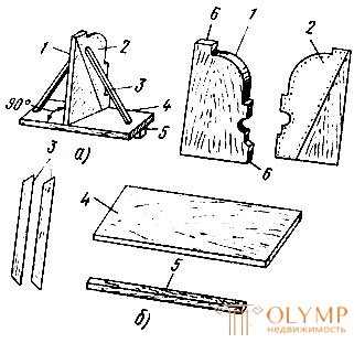
Fig. 61. Template (a) and its parts (b): 1 - profiled boards, 2 - steel profile, 3 - struts, 4 - sled, 5 - polozok, 6 - excuses
After transferring to the board the profile of thrust and excuses, the board is cut at the square in order that it is at a right angle in the template with respect to the sled. Then the profile is cut out and one side of the profile board is cut or beveled at an angle of 30-40 ° according to the completed breakage. Thus, on the profile board two sides are formed - cut off ("on gloss") and not cut off ("on sdir"). Made profile board forged roofing steel. To do this, cut out the same profile from steel as on the board, apply it to the non-beveled side of the board and nail it with plaster nails 10-20 mm indented 5 mm from the edge of the profile. The steel profile either coincides with the wooden one, or stands 1-2 mm behind it. In the process of drawing, the solution is formed or drawn out with a steel profile, the wooden one serves as a supporting frame. Therefore, the contour of the metal profile must be particularly accurate.
A sled is a planed board 1.5 times as long as a profile board with a width of 100-1 mm and more. Longer slides give the template stability when stretching, but leave long corners that have to be cut by hand. The skids are fastened to the sled, i.e. square or rectangular planed bar equal to the length of the sled. The struts are round planed sticks.
The template is assembled in this sequence. In the center of the slide, the profile board is placed so that the bottom excuse is flush with their edge. With the help of two or three 75- 100 mm nails driven from the bottom of the sled, the profile board is fixed. For stronger fastening in a sled choose a groove, put a profile board there and fix it with nails. Then, struts are nailed to the profile board and sled, which not only hold the profile board, but are also handles. Polozok nailed from the bottom side of the sled. Its purpose is to precisely guide the template according to the rules and not to allow it to be pressed into the cravings. In the manufacture of the template, the skids are fixed temporarily with nails, finally it is nailed according to the hung lower rules.
Hanging the rules (Fig. 62). When drawing out the rules, rules 2 and 3 are intended to move patterns 1 along them. For the lower rule, use rectangular bars with a section of 40 x 60 mm and for the top one - 25 x 60 mm. When pulling in large rooms, the rules are joined by ends, which are slightly bevelled so that the pattern runs smoothly in these places without any jumps. The lower rules are hung from the corner to the corner of the room, the upper ones are shorter than the lower ones by the length of the sled, so that the template can be inserted or removed in any corner.
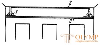
Fig. 62. Template (1) and setting rules (2, 3):
The rules are fixed (Fig. 63) with the help of clips 1, 5. Rules can be nailed to wooden walls and ceilings, and sometimes they are frozen to brick and concrete walls with plaster mortar.
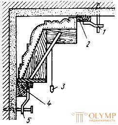
Fig. 63. Template installation and fastening rules: 1, 5 - clamps, 2, 4 - rules, 3 - plumb
Rules hang as follows. After applying the primer on the ceiling and top of the walls, place the template in the corners of the walls and the ceiling and place it on a level or plumb, then make marks on the plaster: on the upper end of the profile board - on the ceiling, and on the underside of the slide - on the wall. Rules 2 and 4 are preliminarily attached to these marks. After that, a pattern and rules are set on the level or plumb line 3 in order to avoid trailing. Having established the template, the rules correct and finally strengthen, and a skid is nailed to the sled.
First, the rules are set on a wall that has windows. The lower rules are hung and checked by level, and the upper ones by template, which is arranged by level or plumb line. Then the rules are hung on the opposite wall in the same sequence as described above.
Having stretched the traction, before removing the lower rules, they make a mark on the upper edge in the corners on their plaster. The lower rules on the other two walls are hung only on these marks, and the upper ones - on a pattern. If you do not make such marks and make a mistake when hanging the lower rules, the thrust will be at different levels and will not converge in the corners when cutting.
If the windows are on two adjacent walls (corner room), the work is performed primarily on these walls.
If a lot of mortar is required to carry out the thrust (well-shaped cornice), the surfaces are additionally prepared by hammering nails and braiding them with wire. At the same time, nail heads should not reach the profile board template by at least 20 mm.
Extrusion Hooking up the rules, proceed to the stretching of the load. This work is more convenient to perform together (Fig. 64). Both plasterers apply the solution at the place of drawing, then one takes the pattern, inserts it into the rules and smoothly leads, and the second holds the falcon under the pattern and collects the solution cut by the profile board.
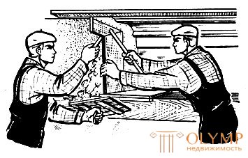
Fig. 64. Pulling traction (cornice)
The work is carried out in such a sequence. Between the rules, the applied primer is moistened with water, a creamy solution is prepared, it is applied with a layer of not more than 10 mm. Then prepare a thick solution, put it in the husk and other well-defined places of thrust. Sinks are smeared with a solution in the first place, in order to quickly generate cravings. The application of a gray mortar or soil and pulling with a pattern is repeated until a completely smooth traction is obtained, with no shells and roughness, with the smallest breaking off completely formed.
After pulling "on sdir" template, the rules and the box is cleaned from the solution and washed with water so that sand does not get into the covering layer, from which scratches will remain on the weave:
A plaster mortar for lime-gypsum plasters is prepared from 3 parts of lime dough and 0.5-1 parts of gypsum, previously sifted through a sieve with a cell size of 1 x 1 mm. The density of the skimming solution should be creamy. The prepared solution is allowed to thicken slightly, then it is stirred to make it more plastic. When pulling on the covering layer of the "gum" pattern, they lead "to gloss" - forward with the beveled side, which smoothes the solution better. When pulling out the “beat”, it is necessary to stretch the template without stopping along the entire length of the rules in order to avoid the formation of joints on the bollard. After pulling the "beat out" on it should not be shells, scratches and traces of soil. Sometimes the application of a covering solution and pulling of "Izbel" is repeated 2-3 times.
The sequence of pulling out of the lime-cement and cement mortars is the same, but only the pull "on the peg" does not pull, because these solutions do not increase in volume but decrease in volume. Traction "Izbel" can pull out of the cement or cement-lime mortar with fine-grained sand. It is not recommended to make a layer of pure cement paste or cement on lime milk, as it dries out, it becomes covered with cracks and is not always smooth and clean.
In order to improve the quality of cement and cement-lime mortars, they are recommended to be applied in layers no thicker than 10 mm, and the applied mortar should not be powdered with dry cement or a mixture to drain it, as this reduces the strength of the mortar.
It should be borne in mind that cement and cement-lime mortars seize slowly, so the work should be organized so that the time required for setting the mortar, was used to perform other types of work.
Cutting corners . After stretching the undersized parts remain in the corners. Cutting corners is a tricky job requiring high craftsmanship. They cut the corners by hand with a ruler and cutting or corner patterns, and use small pencuts for rubbing.
Cutting by hand . Rulers for cutting corners are made of wood. They are unilateral and bilateral. One edge — the edge of a ruler — is made rectangular, the second is rounded. The rectangular side cut off the solution on the rectangular fractures, and the rounded off - on the curvilinear. The ends of the ruler are cut at an angle of 45 ° and nailed to them on the same level with the plane of the ribs sharpened steel plate-cutter of exactly the same shape that the ribs have. The longer the ruler, the more convenient it is to work, as it cuts the solution more accurately. A narrow ruler is convenient for cutting plastics from small breakages.
Corners cut in a certain sequence. First of all, a soil solution is thrown at an angle of 10–15 mm below the level of an elongated thrust. The applied soil is shaped into a pull. Then apply a spray solution on the ground above the main thrust by 5 mm.
After the solution grabs a little, proceed to cutting the corners - cutting the solution with a ruler. The line is attached to the previously stretched billet and smoothly propelled along the thrust with a chisel forward.
When cutting the solution, the ruler is pressed to the surface of the elongated thrust so that it goes smoothly, and its tool does not penetrate into the thickness of the applied solution.
The ruler cuts off the excess solution from the corner, and after it a bummer of a certain shape remains (fig. 65). After cutting off the mortar with a ruler, architectural lines of breakage, located on two different sides of the thrust, should exactly converge in the corner husk.
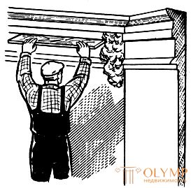
Fig. 65. Cutting the corner with a ruler
After cutting off the solution, the corners have a roughness, in addition, they are not accurate enough, so they are recommended to be corrected by rubbing with a scraper. As a result of the cutting, all corners should be in the same plane with the elongated bollard. The pod must be strictly vertical. To do this, it is checked with a plumb line, corrected, and a thin line is drawn through the end of the cut, which sharply highlights the husk.
The corner template with one profile board (Fig. 66a) has a sled 1 in the form of a triangle; profile board 3 is set in a slide at an angle of 45 °: Therefore, the breaks going along the ceiling should be increased in length by 40%. In a template with two profile boards (Fig. 66, b), the latter are set at an angle of 90 ° to one another.
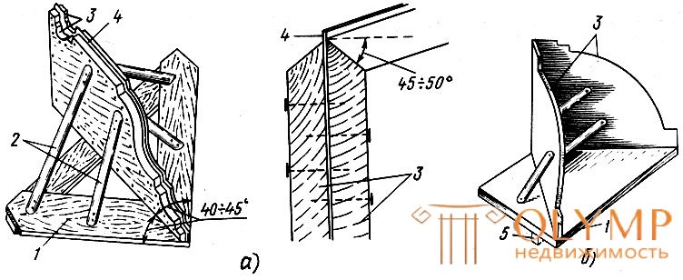
Fig. 66. Corner patterns: a - with one profile board, b - with two profile boards; 1 - sled, 2 - struts, 3 - profile 4 - steel profile, 5 - polozok
For cutting corners, also use a collapsible template (Fig. 67), which consists of several separate wooden semi-grates with steel profiles nailed up and with cut out profiles. One of the half tinkers 1 is designed to pull out the ceiling draft, the other 2 - for the corner (middle), the third 3 - for the wall part. The length of wooden semi-grates of the collapsible template is 400-500 mm. The ends of them are cut at an angle, so with a scribble you can reach the angle to the husk itself.
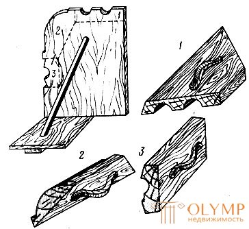
Fig. 67. Collapsible corner cutting template: 1 - ceiling part, 2 - corner (middle) part, 3 - wall part
Folding patterns angles are cut as follows. A solution is applied to one of the corners of the ceiling, a template is attached to the trowel and pushed it forward, shaping the applied solution. The same is done with the other ceiling part, as well as with the corner and wall parts of the corner.
Cutting raskrepovok . Traction on the sides of the pilasters are called straightening. Their cutting is one of the most difficult and laborious works. That side of the pilaster, which is parallel to the wall, is pulled in the usual way according to the hung rules.
When cutting raskrepovok primarily finish up the ends of the pilasters on the pilaster and on the walls until the raskrepovki and rub them with a scraper. Then the solution is applied to the rasprepovka and cut it at the square. On the cut side of the line carry the line and cut them raskrepovki. The solution is cut off with a ruler, trimmed with a cut, and rubbed with trowels so that the thrust on rasprepovke was the same as the pattern stretched.
The following method is recommended for more accurate and faster debugging 1 (fig. 68). From plywood or cardboard cut out the profile 3 pulling thrust. To cut off on raskrepovke solution 2 put this profile so that it coincides with the profile of the extended thrust. The profile is surrounded by the end of the nail, which leaves a trace of the profile on the solution. From the characteristic points of the trace is carried out on the solution raskrepovki lines, which must converge with the burden. Along these lines, the excess solution is cut off with a ruler and a cut, and then the resulting break-offs are rubbed with scribes.
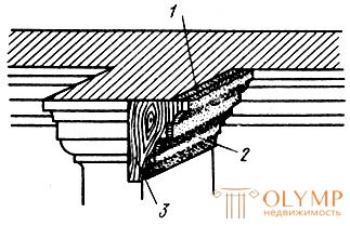
Fig. 68. Cutting raskrepovok: 1 - raskrepovka, 2 - solution, 3 - plywood or cardboard profile
When the length of the strips is 20 cm, it is advisable to pull them out with a one-sided template, which is used to draw the rods between the pilasters (see fig. 70).
Что бы оставить комментарий войдите
Комментарии (0)