13.1. Transition curve
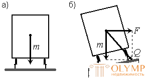
Direct conjugation of a straight leg with a circular curve leads to the fact that while the train is moving at the junction points, a centrifugal force F suddenly appears (Fig. 88), directly proportional to the square of the speed of movement υ and inversely proportional to the radius of the curve R


Fig.88. The forces acting on the composition on the straight (a) and curve (b) section of the railway track
Sharp centrifugal force on rolling stock and railway, especially at high speeds, can lead to an emergency. To prevent this from happening, for a gradual increase in centrifugal force, the end points of the circular curves are mated with straight lines using so-called transition curves whose radius changes from infinity (at the beginning of the transition curve) to the radius of the circular curve (at the interface point with the latter). In addition, within the transitional curves, the elevation of the outer rail to the inside mark is carried out. The elevation of the outer rail is calculated for each curve, depending on the average weight of the train and the estimated speed of movement.
On the railways of Russia, the transition curves are constructed according to a radial spiral (clothoid) with a linear curvature change
 where
where  - variable radius of curvature of the spiral in meters; c is a constant in square meters, shows the rate of development of the radius of curvature;
  - the current length of the transition curve.
With the length of the transition curve  radius of curvature
  ; at
; at  equal to the design length of the transition curve
  the radius of curvature of the spiral is equal to the radius of the circular curve:
  .
.
Transition curves take the standard length from 20 to 200 m, multiples of 20 m, depending on the radius of the circular curve and the speed of trains.
When inserting transition curves, the radius of the circular curve decreases by the amount of shift. In order for the radius of the latter not to decrease when the transitional and circular curves are conjugated, the center of the circular curve of the design radius is shifted inward along the bisector of the angle formed by the directions of the route.

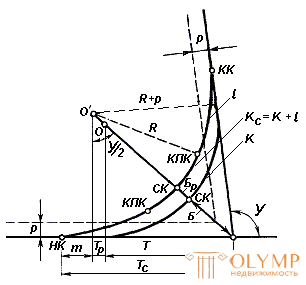
Fig. 89. Circular and transition curves
The diagram (Fig. 89) shows the elements of the transition curve: the increment of the tangent m , the increment of the radius p , the increment of the curve Tp and the increment of the bisector Br , which is calculated by the formulas
 ,
,
 ,
,
 ,
,
 .
.
At the device of a transitional curve, the center of the circular curve is shifted by the value of p , and the point of the beginning and end of the curve by the value of m .
6.2. Railway curve, its elements and main points
In accordance with the design standards for railways, on railings, railway curves should be arranged in the form of a combination of a circular curve with two transition curves (see Fig. 89).
The railway curve has 7 elements and 6 main points.
Main points:
1. WU - the top of the corner.
2. NC - the beginning of the railway curve.
3. QC - the end of the railway curve.
4. SC - the middle of the railway curve.
5. KPK1 - the end of the transition curve first.
6. NPK2 - the beginning of the second transition curve.
Elements of the railway curve:
1. Y - the angle of rotation of the curve (calculated).
2. R is the radius of the circular curve (selectable).
3  - the length of the transition curve. Its choice depends on the category of the road and the radius of the curve.
4. TC - the tangent of the railway curve. Determined by the formula
Tc = T + Tr + m.
5. Кс - the length of the railway curve
Kc = K +  ,
,
 ,
,
 ,
,
where β is the angle of half of the transition curve
 ,
,
 .
.
6. BS - bisector of the railway curve
Bs = B + Br.
7. D with - Domer railway curve
Ds = 2Ts - Ks,
To control the domer is calculated by the following formula

6.3. Calculating the stationing of the main points of the railway curve and the breakdown of the curve at the main points on the ground
The calculation of the picket of the main points of the railway curve is performed by the same formulas as for the circular curve.
If necessary, calculate the station value of the points of the end and the beginning of the transition curves by the formulas
KPK1 = NC +  and NPK2 = KK -
  .
.
The breakdown of the curve at major points on the ground is produced as well as for a circular curve.
13.4. Questions for self-control
1. What is a transition curve? How and why does it work?
2. What are the elements of the transition curve.
3. How does the railway curve differ from a circular curve?
4. What are the elements and the main points characterized by the railway curve?
5. How are the elements of the railway curve determined?
Что бы оставить комментарий войдите
Комментарии (0)