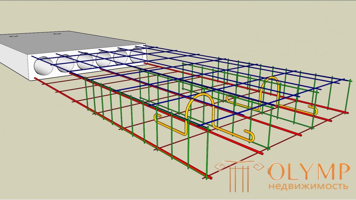

The overlap must be well able to withstand the bending stress, therefore, the hardening of the plates must comply with all the calculations. The slab should have two reinforcing mesh (bottom row and top). The bars of the reinforcement should be directed along and across the span of the beam. Rebar spacing for industrial buildings is set after determining all loads and norms. By pitch, we mean the same distance between the bars of the reinforcement to evenly distribute all the loads.
Reinforced mesh is laid in the plate thickness of 2.5-3 cm from its surface. For slabs, you can use a finished welded mesh or make yourself - tie up all the rods at all the intersections with a special knitting wire. In order to avoid breaks in the reinforcement ligament, it is not recommended to self-cook the cores of the floor slab, as strong breaks may occur in the place of accumulation of stresses. This type of reinforcement is used on a production scale, where the welded mesh is processed to relieve stresses.
It is necessary to install clamps between the rows of reinforcing mesh (lower and upper). These are special reinforcement mesh dividers (vertical elements), they are needed for uniform installation of grids inside the slab. So you can maintain one distance between the two grids. The separator can be put any - a loop or a curved hook, they are also located in the design with a certain pitch. The schematic arrangement of the reinforcement is represented in the drawing. All edges of the slab must additionally contain reinforced reinforcement with L-shaped and U-shaped elements. In places where the slab supports on the beams - especially.

If the slabs are large and monolithic and are supported by beams around the perimeter, then additional reinforcement is made around the entire perimeter. The lower part experiences a tensile force, and the upper, on the contrary, is only compressive. It is better to strengthen the lower reinforcement (to make it thicker), since the main tensile load is concentrated there. There are no special requirements for a standard span of 6 meters, if it is greater than this value (the distance from one support to another), then the reinforcement reinforcement requirements (strength of the concrete slab) should be revised.
If the size exceeds 6 m, it is necessary to make a technical calculation of all loads, and only after that it will be seen whether to reinforce the slab additionally or not. Usually the reinforcement goes at the plate support points (reinforcement of the upper layers), and the middle of the plate is reinforced in the lower layer with reinforcement.
Metal rods should be cast (without breaks). If the rods consist of two parts, then the overlap is considered by the formula - d * 40. The value of d is the diameter of the reinforcement. If it is assumed that it is 20 mm, in this case the overlap is 800 mm.
For reinforced concrete slabs, steel reinforcement A3 is used. The recommended diameter according to the norms of SNiP from 8-14mm. After all recalculations, you can make adjustments to the drawing plan. According to the general standards for the installation of floor slabs up to 6 m, it is recommended to take a reinforcement spacing of 200 mm by 200 mm, the thickness of the slab should also be taken 200 mm. In this case, the upper grid will be with a diameter of 8 mm rods, and the top 12 mm.
Plates of this type are used to cover single-storey industrial buildings with a step of building structures of 6m.
Basically, ribbed plates of size 3 × 6m; 1.5 × 6m plates are used only as additional in places where snow cover accumulates. The plates are distinguished by the magnitude of the calculated load, depending on the mass of the panel and roof, the area of snow load, the mass of ventilation devices.
Plates after welding the embedded parts of the monolithing seams form horizontal diaphragms that ensure the spatial operation of the frame, as well as the stability of the upper chords of truss structures. Diaphragms transmit wind load and longitudinal braking of the cranes to the coupling block of columns.
The plates have a U-shaped cross section and consist of a shelf with a thickness of 30 m, transverse ribs of trapezoidal section with a height of 150 mm, located through 1 m in plates with a width of 3 m and through 1.5 m in plates with a width of 1.5 m, and two longitudinal edges with a height of 300 mm.
The shelf is reinforced with welded meshes С-1 made of cold-drawn wire of class B-1. The longitudinal bars of the frameworks Kp-1 and Kp-2 of the ribs are made of steel of a periodic profile of class A-III, transverse of cold-drawn wire of class B-1. The armature of the longitudinal ribs is tense. Its possible options: core periodicity of the profile of steel grades. A-IY, A-Y, thermally hardened classes At-IY, At-Y; highly durable wire diameter 5mm class BP-II; reinforcing ropes with a diameter of 12 m and 15m class K-7.
Characteristic of 6m spans and consumption of materials.
Plate size | Brand of concrete | Weight (t) | Concrete consumption (m3) | Steel consumption (kg) | |
strained arm. A-IY, A-Y | Total | ||||
3 | B-25 | 2.7 | 1.1 | 11 - 48 | 66 - 150 |
1.5 | 1.5 | 0.6 | 11 -30 | 39 - 80 | |
(The steel consumption limits indicated in the table are determined by the magnitude of the calculated load, varying within 175-775 kg / m² (excluding slab).
In addition, welded meshes C-3 of class B-1 cold-drawn wire are additionally placed on the support sections of the longitudinal ribs. In places of conjugation of longitudinal and end transverse ribs, welded meshes С-2 are vertically installed to limit the width of crack opening during the release of pre-stressed reinforcement. Woot reinforced obliquely located welded mesh C-4 and C-5. Rebar grids - cold-drawn wire class B-1.
Embedded parts of MN1 are installed on the supports of the longitudinal edges, which, in order to ensure the hardness of the coating disk, are welded to the embedded parts of the truss structures.
The shelf of the slab is calculated as a multi-span continuous system, loaded with uniformly distributed and concentrated loads; with a slab width of 3 m - according to the beam scheme, 1.5 m - as a slab supported along the contour. The cross and longitudinal edges are calculated as beams of T-shaped section, free-lying on 2 supports, loaded with a uniformly distributed load. In addition, when calculating the transverse edges take into account the concentrated load of the weight of the worker with the tool. The loads are constant (the weight of the roof, the weight of the slab) and temporary (snow) are taken as evenly distributed or triangular in shape for transverse ribs with plates supported along the contour. Efforts in sections of the shelf and edges determined by the methods of building mechanics. Plate deflections are calculated using the formula of a curved axis, taking into account the long
the impact of part of the load and bending from the preliminary compression of concrete. Concrete slabs in the working position, the reinforcement is mechanically tensioned on the supports of the stand.
Что бы оставить комментарий войдите
Комментарии (0)