The general principles for designing prestressed structures are the same as for elements without prestressing.
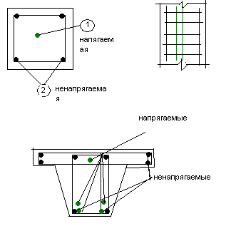
For elements of centrally stretched, centrally compressed, as well as eccentrically stretched with a small eccentricity of the longitudinal force, you can take a rectangular section
 For bent elements that are eccentrically compressed and eccentrically stretched with a large eccentricity, cross sections with developed stretched and compressed zones of concrete should be used, I-beams or T-bars with a shelf located in the compressed zone.
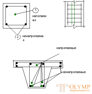
Longitudinal non-stressed reinforcement should be placed closer to the outer surface of the structure than the pre-stressed one, so that the pre-stressed reinforcement is inside the transverse reinforcement contour (clamps).
In elements with longitudinal reinforcement tensioned onto concrete and located in channels, the thickness of the protective layer against the surface of the channel should be at least 20 mm. when bundles, strands or rods are located in one channel, the thickness of the protective layer should be at least 80 for the side walls, and not less than 60 mm for the lower walls.
Clearances in the light can be individual tensioned rods, beams and strands should be no less than the diameter of the reinforcement and not less than 25 mm.
To ensure the reliability of the transfer compressing force on the concrete at the ends of pre-stressed structures, indirect reinforcement is installed in the form of welded meshes. 
The main provisions of the calculation.
General information.
Pre-stressed reinforced concrete structures are calculated as well as elements without prestressing in two groups of limiting states. When calculating according to the first limiting state, in addition to the general strength calculation, the local strength of the concrete elements is checked against the effect of the concentrated forces of pre-stressed reinforcement. Also check the strength of the element during its compression, transportation, installation.
When calculating the deformations take into account the reverse bend of the structures from the preliminary compression of concrete.
When calculating the crack resistance, prestressed structures, depending on the required durability, working conditions and the type of reinforcement used, are divided into three categories.
Category 1 includes structures in which it is necessary to ensure impermeability (pressure pipes, tanks). Calculation of crack resistance
(for the formation of cracks) such structures are produced on the effect of stretched stresses (constant, long-term and short-term with a coefficient of reliability for the load yf> 1) in combination with the prestress. In the construction of the first category, normal, inclined and longitudinal cracks are not allowed.
The second category includes structures in which the formation of cracks is allowed at design loads, and at standard loads a short opening of normal and inclined cracks is limited in width.
The third category includes structures in which the formation of cracks is allowed under normal loads. Maximum permissible width
crack opening varies depending on the category and compilation of 0.1-0.4mm.
Pre-stressing the reinforcement .
In the design of prestressing structures designate taking into account the mechanical properties of reinforcing steel. Controlled stresses should not be> the elastic limit of the steel, but not too low, since the weakly stretched reinforcement will be ineffective.
In prestressing reinforcement Gsp u G / sp, respectively, in prestressing reinforcement S and S / is prescribed taking into account the prestress, the following conditions must be met for rod and wire reinforcement.
Gsp + ∆Gsp≤Rs, Sich and Gsp-∆bsp≥0.3Rs, Sich
In the mechanical method of tensioning the reinforcement, ∆Gsp = 0.05bsp is taken, and in the electrothermal method of tension, MPa
∆Gsp = 30 + 360 / L, where L is the length of the tensioned rod (m). Gcon preload and Gcon / minus preload voltage losses.
Loss of pre-stress in the valve.
The initial prestresses in the reinforcement do not remain constant, they decrease with time due to a number of reasons. Stresses fall as with the tension of the reinforcement on the stops, and under tension on the hardened concrete. There are first prestress losses in the reinforcement occurring during the manufacture of the element and the reduction of concrete, and the second loss occurring after the compression of concrete.
A. The first loss.
1. From stress relaxation in reinforcement under tension, they depend on the tension method and the type of reinforcement:
with the mechanical method of tension, MPa: high-strength reinforcing wire and ropes:
G1 = [0.22 (Gsp / Gs, Sich) -0.1] * Gsp;
Rod fittings:
G1 = 0.1Gsp-20
If the calculation of the losses from stress relaxation is negative, they should be taken equal to zero.
2. From the temperature difference, that is, from the difference in temperature of the tensioned reinforcement in the heating zone and the device that perceives the tension force during the heating of concrete:
For concrete classes B15 ... B40 G2 = 1.2∆t.
For concrete classes B45 and above G2 = 1.0∆t,
where ∆t is the difference between the temperature of the heated reinforcement and fixed stops (all heating zones) perceiving the tension force, 0С; in the absence of accurate data take ∆t = 650С.
3. From the deformation of the anchors located heads, the displacement of the rods in the clamps or clamps.
G3 = (∆e / e) Es, where ∆e- compression of pressed-in washers, removal of the planted heads taken to be 2mm; e-length of the heated rod; Es-modulus of elastic reinforcement.
4. From the friction of the reinforcement on the channel walls or on the surface of the concrete of structures with tension on the concrete: G4
From the deformation of the steel form in the manufacture of prestress reinforced concrete structures:
G5 = תּ (∆ e / e) * Es, where
תּ- coefficient determined by the formula
תּ = (n-1) / 2n
e- the distance between the outer edges of the stops
∆e is the reduction of the stops on the line of action of the force p, determined from the calculation of the shape deformation, n is the number of tensioned rods.
6. Creep loss of concrete, depends on the class of concrete, they develop the first 2-3 hours after compression.
G0 = 40 (Gvr / Rvr), where
Gvr-compressive stresses in concrete in the stage of preliminary compression.
B. The second loss.
7. Losses from stress relaxation. Relaxation is the reduction of stresses without changing strains, due to the structure of steel. These losses are taken the same as when tensioning the stops, that is, G7 = G1.
8. From shrinkage of the concrete and shortening of the element (depending on the type of concrete, the method of tension of the reinforcement) G8
9. Creep Concrete G9
Total losses Gsn = Gsn1 + Gsn2; in all cases, they need to be taken not <100 MPa.
Calculation of the strength of centrally stretched elements.
During the operation of centrally stretched elements under load, as well as the bending of elements, there are three stages of the stress state: stage 1 - before cracking in concrete, stage 2 - after cracking and stage 3 - breaking.
By the time of destruction, the element is cut through through cracks. In accordance with this, tensile concrete is not taken into account in stretched concrete, and long-lasting force is perceived only by the prestressed reinforcement Asp and the non-stressed reinforcement As. The strength of the centrally stretched element will be ensured under the condition
N≤∂sб * Rs * Asp + Rs * As,
Where sб-coefficient taking into account the work of high-strength reinforcement at stresses above the conventional yield strength.
Calculation of the formation of cracks. The crack resistance of centrally stretched prestresses of elements 1 and 2 category will be provided subject to the condition
N≤Nт, where
N- for structures of the 1st category of cracks - force from the design stress; for designs of the 2nd category effort from standard tension.
NT is the force perceived by the element before cracking.
Calculation of deformations.
The deflections of prestressed bending elements that do not have cracks in the stretched zone, is determined by the formula:
f = 5/384 * n * L4 / Bk, where
Bk-stiffness
Bk = 0.85 * E * I (I = c * h3 / 12)
E - modulus of elasticity of concrete
Что бы оставить комментарий войдите
Комментарии (0)