
The strength of the bent element along the normal to the axis of the element section
calculated by stage 2 of the stress-strain state. At the same time, we replace the curvilinear diagram of the stress in the straight concrete having the same area.
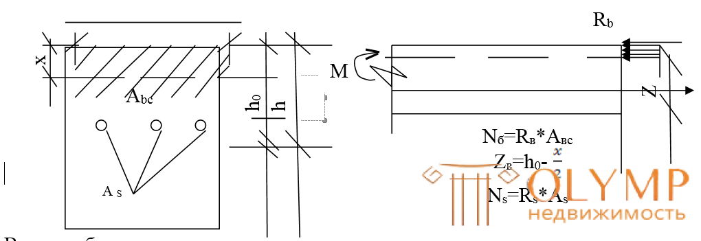
Consider a rectangular section with a single reinforcement, i.e. section in which the working fittings is located only in the stretched zone.
We introduce the notation:
b- section width (cm)
h- section height (cm)
h0 = ha - working (useful section height)
a is the distance from the stretched edge of the section to the center of gravity of the stretched reinforcement As (a = 3 ÷ 4 cm in the beams; a = 1.5 ÷ 2 cm in the slabs)
As- cross-sectional area of tensile reinforcement (cm2)
Avs- the cross-sectional area of the compressed zone of the section (cm2)
X - height of the compressed zone of the section (cm) - (distance from the compressed edge of the section to the neutral axis)
Zb is the distance from the center of gravity of the area of the compressed zone of concrete to the center of gravity of the area of the tensioned reinforcement — the shoulder of the internal pair of forces.
If the amount of reinforcement does not exceed a certain specific value (normally reinforced beam), the destruction begins with the yield strength of the reinforcement. In the cross section, cracks strongly open, sharp deflections increase, and only after that the concrete of the compressed zone is crushed.
If the amount of reinforcement is greater than a certain size (re-reinforced beam), then the destruction begins with a compressed zone of concrete. The tension in the tensioned reinforcement does not reach the limiting resistances.  m, i.e. the reinforcement will not be used completely. Depending on the reasons for the exhaustion of the carrying capacity, there are 2 cases of the calculation of bending moments as normal. cross section:
SL.1 - in the compressed concrete and tensioned reinforcement the limiting values of resistance Rв and Rs are reached
next 2 - in the compressed concrete, the limit values Rb are reached, and in the tensioned reinforcement, instead of Rs, some lower voltage acts  s.
s.
The boundary condition between cases 1 and 2 is set depending on the relative height of the compressed zone of concrete  (i.e. the ratio of the height of the compressed zone of concrete x to the working height
  ).If a
  where
where  - some boundary value
  then we have 1 case, if
 , then we have the 2nd case. Boundary value determined by table 3.2 (page 90) Tsai or tab. 5 "Printouts"
The basis for the design of the section is the calculation on the occasion of 1, since Sections that work on occasion 2 do not allow for the full use of reinforcement, and they are trying to avoid designing such sections.
For a rectangular section with a single reinforcement, the internal forces in the limit state are equal: Ns = Rs  As, in tensile reinforcement, Nb = Rb Avs-in compressed concrete is assumed to be rectangular (instead of the actual curvilinear).
For the calculation, the two basic conditions of statics are used: the equality to zero of the sum of the projections of all forces on the element axis (  ) and the sum of all moments about the axis passing through the point of application of the resultant force in the reinforcement S (
  M = 0)
the position of the neutral axis is determined, and, consequently, the area of the compressed zone Авс = in  x Rs As = Rv at x or Rs A s = Rv at x (1) M = 0 determine M = Rv at x (h0 - 0.5x)
 or M = Rs As (h0 - 0.5x).
The strength of the section will be ensured if the external moment “M” does not exceed the limiting value of the moment of internal forces (from formula 2), therefore the final strength condition will be:
M  Rв at x (h0 - 0.5x) or M Rs As (h0 - 0.5x) (2)
Of great importance when calculating sections are the height of the compressed zone “x” and the working height of section “h0” (i.e. the total height “h” minus the distance “a” from the resultant force in reinforcement A to the stretched beam face). The ratio of these values  called the relative height of the compressed zone. It is recommended to design flexural elements so that the relative height of the compressed zone did not exceed the value i.e. that case 1 always happens.
From formula (1) you can find the values characterizing the height of the compressed zone: x =  We divide both sides by h0,
 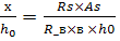 denote
 =
=  - reinforcement ratio - degree of saturation of the section with reinforcement.
 from this formula we see that with increasing
reinforcement ratio " "Grows and the relative height of the compressed zone" "And the second case of stage 3 may occur, which is unacceptable, therefore, the condition must be checked
.
Often use the concept of percentage reinforcement 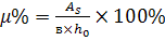 The following percent of reinforcement is recommended from the condition for optimizing the cost of the reinforced concrete element:
 (in beams)
 (in plates)
At the same time, the minimum percentage of reinforcement is set, which is 0.05% for bending elements.
To reduce calculations in the calculation of rectangular sections used auxiliary tables.
For the tabulation of the formula (1) and (2) lead to the form
 (3)
(3)
 (4) where
  ; η = 1-0.5
task number 1
Given:
beam rectangular section = 25cm;
h = 50cm;
bending moment in the beam from the design loads Μ = 172 kNm;
concrete of class B15; Äbi = 1;
fittings A III
To determine: As reinforcement section area:
Determine the calculated data:
According to table 2.3 (Tsai) = Rv = 8.5 MPa (v.1 printouts)
According to table 2.8 (Tsai) = Rs = 365 MPa (v.2 printouts)
Take a = 3cm
h0 = h - a = 50-3 = 47cm
Define A0:
A0 = 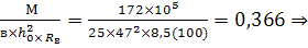 η = 0.755
As = 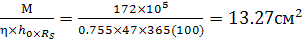 Accepted: 2¯22АIII + 2¯20AIII сAsfact. = 13.9
Что бы оставить комментарий войдите
Комментарии (0)