
The dimensions of the foundations are prescribed on the basis of the condition that the average pressure at its sole does not exceed the values at which the operational suitability of the structure is impaired. This is ensured by the calculation of the bases in the two previous states. For non-rock soils, the main limiting state is the second, i.e. calculation for deformations. Thus, the dimensions of the foundation are prescribed from the condition of providing such a draft that does not exceed the limits for this structure, i.e. When calculating the deformations, the following condition must be met: S≤ Su, where
S-compatible deformation of the base and structures;
Su-ultimate joint deformation of the foundation and structures (see Appendix 4 of the SNIP "Foundations and Foundations")
This condition can be fulfilled not only by selecting a specific one. the size of the footing of the foundations, but also by improving the properties of the base soils, for example, compaction or consolidation.
Estimated soil resistance .
It is determined by the formula:
one)  where
where
 and
and  - the coefficients of working conditions taken on the table. 1.4 p 152 Berlin
K- coefficient, readable = 1, if the strength characteristics of the soil "  and c ”are determined by direct testing and equal to 1.1, when these characteristics are taken from reference tables;
M  ; Mg; Mc - coefficients taken from table. 1,3 p.151 account. Berlin depending on the angle of internal friction.
k  –Coefficient equal to:
with V <10 m => k  = 1, at В≥10 m, k = Z0 / b +0.2, (Zo = 8m);
V-width of the base of the basement (m);
 - averaged design specific gravity of soils lying below the base of the foundations (kN / M3)
 - the same, lying above the sole;
d is the depth of laying the foundations of baseless structures or external and internal foundations from the basement floor, defined by the formula:
d1 = hs + hcf 
hs - soil layer thickness above the basement basement from the basement (m)
hcf - basement floor thickness (m)
cf is the calculated specific weight of the basement floor construction, kN / m3
dv - basement depth - distance from the level of planning to the basement floor (m)
(For a structure with a basement of width of ≤20 m and a depth of more than 2 m is taken
dv = 2; with a basement width of B> 20m-dv = 0).
 - specific adhesion in kPa or MPa.
As can be seen from formula 1, the value of R depends not only on the physico-mechanical characteristics of the base soils, but also on the desired geometric dimensions of the foundation, the width and depth of its foundation. Therefore, the determination of the size of the basement, asking pre-some initial size.
Example number 1.
Determine the design resistance of the soil base for the strip foundation width = 1.4 m with the following initial data:
projected building 9-storey
The ratio of length to height is L / H = 1.5. The depth of the foundation from the level of planning for constructive reasons adopted d = 1.7 m. The building has a basement width B = 12 m and depth d = 1.2 m. The thickness of the soil layer from the bottom of the foundation to the basement floor is hs = 0.3 m, hsf = 0.2m, and the specific gravity of the concrete = 23kn / m3
The site is composed of small medium-density fine sands, the porosity coefficient is l = 0.65; ground weight below the sole = 18kn / m3,
above the sole = 17kn / m3. The normative values of the strength and deformation characteristics are taken from reference tables:
Yn = YII = 320; Cn = CII = 2kPa; E = 28 MPa
Decision.
To calculate the calculated soil resistance of the base according to the formula (1), we take: for fine, low-moisture sand with L / H = 1.5 =>  = 1.3,
  = 1.3
= 1.3
on the table. 4 (SNIP 2.02.01-83) with = 32o =>, M  = 1.34; Mg = 6.34; Mc = 8.55
since the values of soil strength characteristics are taken from reference tables, k = 1.1. At = 1.4m <10m => kz = 1
the reduced depth of the foundation from the basement floor of the formula 2.
d1 = hs + hcf  = 0.3 + 0.2
  = 0.57m
formula 1 determines the calculation of the resistance of the soil
R = 
= [1.34 1 1.4 18 + 6.34 0.57 17+ (6.34-1) 1.2 17 + 8.55 2] = 1.54 2.21 = 340 kPa = 0.34 mPa
Example
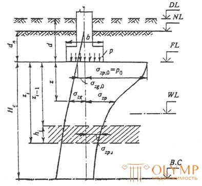
Fig.6.1. The distribution of vertical stresses in a linearly deformable half-space
6.1. The draft of the base s using the design scheme in the form of a linearly deformable half-space is determined by the method of layer-by-layer summation using the formula
 ,
,
where b is a dimensionless coefficient equal to 0.8;
szp, is the average value of the additional vertical normal stress in the i -th layer of the soil, equal to the half-sum of the indicated stresses at the top zi- 1 and lower zi boundaries of the layer along the vertical passing through the center of the base of the foundation;
hi and Еi are the thickness and modulus of deformation of the i- th layer of soil, respectively;
n is the number of layers into which the compressible stratum of the base is broken.
In this case, the distribution of vertical normal stresses over the depth of the base is taken in accordance with the scheme shown in Figure 6.1.
Additional vertical stresses at a depth z from the base of the foundation: szp - vertically passing through the center of the base of the foundation:
szp = a p 0,
where a is the coefficient taken from Table 6.1, depending on the shape of the base of the basement, the aspect ratio of the rectangular basement and the relative depth equal to: x = 2 z / b when determining szp ; p 0 = p - szg, 0 - additional vertical pressure on the base; p is the average pressure under the base of the foundation; szg, 0 is the vertical stress due to the weight of the soil at the level of the base of the foundation.
DL - plan mark;
NL - mark the surface of the natural terrain;
FL - mark the bottom of the foundation;
WL - groundwater level;
C.C - lower limit of the compressible stratum;
d and dn are the depth of foundation of the foundation, respectively, from the level of the lay-out and the surface of the natural relief;
b - the width of the foundation;
p is the average pressure under the base of the foundation;
p 0 - additional pressure on the base;
szg and szg, 0 is the vertical stress due to the weight of the soil at a depth z from the base of the foundation and at the level of the base;
szp and szр, 0 - additional vertical stress from external load at depth z from the base of the foundation and at the level of the base;
Нс - depth of compressible strata.
Что бы оставить комментарий войдите
Комментарии (0)