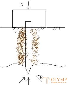
It consists in determining the number of piles f-te <n>, it is necessary for the perception of the vertical load N of the weight of the building, grillage and rational placement of piles in terms of
Pre-determine the design resistance <F> single piles, immersed in the ground to the estimated depth, then the number of piles <n>
Determination of the calculated resistance of a single pile rack .
Pile-stand works in compression as a rod, transferring the load <N> to the ground only with a spike. The friction of the soil on the side surface of the pile is neglected and it is considered that the pile is longitudinally compressed with a constant load N attributable to it from the grillage. The influence of the longitudinal  bending on a pile-rack, surrounded by the ground along the entire length, is also not taken into account and it is assumed that the pile is centrally compressed.
The bearing capacity of the pile is determined from the working conditions of the material from which it is made, and the soil in which it is immersed. To determine the bearing capacity of piles on the ground there are several ways: practical, calculation using formulas and tables, dynamic and according to test data with static load.
The bearing capacity of the soil base of the pile is calculated by the formula:
(2) N≤F /  g = f. where N is the design load transferred to the pile, F is the calculated bearing capacity of the soil of the base of a single pile (otherwise, the bearing capacity of the pile),
  g - reliability coefficient (when determining the bearing capacity of the pile by calculation: based on the result of a dynamic test
  g = 1.4; when it is determined by the field load compression test
  g = 1.25; F is the design load allowed on the pile.
The bearing capacity of the pile-rack on the ground is determined by the formula:
(3) F =  c * r * a where
  c is the working condition coefficient, taken = 1;
A-area bearing pile on the ground;
R is the calculated resistance of compressed soil or rock below the lower end of the piles, assigned for all types of driven piles relying on rock, clay soils of solid consistency, equal to 20 mPa.
The bearing capacity of suspended piles on the ground is determined by two components: the first depends on the resistance of the soil under the lower end of the pile, and the second on the resistance of the soil on its lateral surface:
(4) F =  c * (
c * (  cR * R * A + u∑
  cfi * fi * li) where
  c is the coefficient of working conditions of the pile in the soil = 1,
  cR and
  cfi are the coefficients of the working conditions of the soil, respectively, under the lower end of the pile and along its lateral surface; R is the calculated soil resistance under the lower end of the pile;
A - the area of the pile on the ground, taken over the cross-sectional area of the pile; fi is the calculated resistance of the i-th layer of the base soil along the side surface of the pile; li- thickness of the i-th layer of soil penetrated by the pile.
The design load allowed on a concrete pile is determined by the material according to the formula:
(5) N =  c (
c (  cb * rb * a + rcs * as) where
  c - coefficient of working conditions, taken for piles, manufactured in the soil, equal to 0.6; for the rest = 1,
  cb - coefficient of working conditions of concrete,
Rb is the calculated concrete resistance to compression,
A- cross-sectional area of concrete piles,
Rsc is the calculated resistance of reinforcement to compression,
As- reinforcement area
From these two values choose the smallest, taken as the bearing capacity of the pile.
Calculation and design of pile foundations is carried out in the following sequence:
1. Calculate the load at the level of the planned land mark
2. Assign the depth of the foundation grillage.
3. Select the type, type and designate the preliminary dimensions of the piles.
4. Determine the bearing capacity of piles on the soil and material.
5. Calculate the required number of piles in the foundation by the formula:
(6) n = n  g / Ф, where - reliability coefficient equal to 1.4;
F is the smallest bearing capacity of one pile.
6. Place piles in the plan and arrange a grillage.
Determination of pile bearing capacity.
Example №1

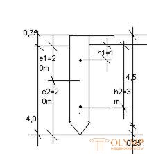
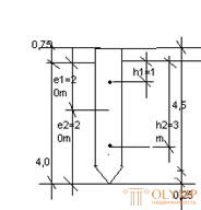
Determine the design load allowed on the reinforced concrete hanging pile on the ground. Brand piles With 4.5-30. pile length is L = 4.5m, width B-0.3m: length l-0.25m. The soil of the foundation is medium sand, medium density, layer thickness 4.5 m. Pile crammed with a diesel hammer to a depth of 4m.
Decision
for t.VI.3 applications VI determine the value of the coefficient  cR = 1 and
  cf = 1.
The pile cross-section area is А = ВхВ = 0.09 m2. the perimeter of the cross section of the pile and = 0.3 * 4 = 1.2 m. According to table VI.1, for sand of average density, medium size and with a pile immersion depth of 4 m, we find R = 3.2 MPa.
To determine the calculated friction force on the lateral surface of the soil layer, penetrated by the pile, divide into layers of a height not exceeding 2 m.
By t.VI.2 with an average depth of the first layer of soil h1 = 1m for sand of medium density, of average size, we define fi = 0.035; we find h2 = 2m + 1m = 3m, f2 = 0.048.
By the formula (4) F =  c * (
c * (  cR * R * A + u∑
  cfi * fi * li) = 1 (1.0 * 3.2 * 0.09 + 1.2 * 1.0 (0.035 * 2 + 0.048 * 2)) (100) = 504000Н = 504kn
Permissible design load on the pile by the formula
(2) N≤F /  g = 504 / 1.4 = 360Kn.
Example number 2.
Determine the design load allowed on the pile C10-40, having a width of = 0.4m, based on the lower end of the rocky soil. The pile is reinforced with longitudinal reinforcement from 4¯18A-II concrete B15  d = 1.4
Decision:
The pile cross-section area A = 0.4 * 0.4 = 0.16 m2.
The bearing capacity of the pile stand on the ground is determined by the formula:
F =  c * R * A, allowable design load on the pile rack
N = F = F /  g = 3200 / 1.4 = 2286kN
 c = 1; R = 20 MPa;
F = 1 * 20 * 1600 (100) = 3200000N = 3200kN = 3.2Mn
The bearing capacity of the pile - stand on the material.
N =  c (
c (  cb * rb * a + rcs * as)
 c = 1
c = 1  cb = 1
Rb = 8.5mPa
Rsc = 280mpa
As = 10.18 cm2 (tab. 7)
N = 1 (1 * 8.5 * 1600 + 280 * 10.18) (100) = 1645040Н = 1645 kN

From the 2 values we choose the lesser: N = 1645kN - the permissible load on the pile - the rack.
LITERATURE
1. Tsai, T.P., Borodin, M.K. “Building Structures” M: stroiizdat, 1984. T.1
2. Tsai, T. P. .. Borodin, M. K. “Building Structures” M .: stroiizdat, 1984. V. 2
3. Pavlova A. I. “Collection of tasks for building structures” M.: Infra-M, 2005.
4. Kuvaldin A.N., Klevtsova G. S. “Examples of calculation of reinforced concrete structures of buildings” M: Stroyizdat, 1976.
5. Berlinov, V.V., Yagupov, B.A., “Examples of Calculation of Bases and Foundations,” Moscow: Stroyizdat, 1986.
6. Gaevoy A.F., Usik S.A. “Course and diploma design of industrial and civil buildings”
L .: Stroyizdat, 1987.
Что бы оставить комментарий войдите
Комментарии (0)