Monolithic reinforced concrete slabs compared with factory-made slabs are more in demand when creating a unique layout of the house, where each of the rooms has its own size. In addition, monolithic products can be made without the use of cranes. But, despite the many advantages of monolithic slabs, quite a few people simply refuse their device. The reason for this is the impossibility of carrying out a proper calculation of the plate at the planning stage. This factor was the impetus for the creation of this article. It describes the whole process of calculating monolithic reinforced concrete floor.
Content
The length of the slab and the design length of the slab are very versatile things. The actual length of the slab can be any. But the calculated length (in other words, the span of the beam, and in our case the floor slab) has completely different values. Span is called the distance in the light (the minimum distance between the most convex parts of adjacent elements) between the bearing walls. To be more precise, this is the length and width of the room calculated from the walls. And by itself, due to the bearing on the wall, in fact the plate will be longer.
It should be noted that the monolithic reinforced concrete slab can be supported on the bearing walls erected from the following materials: brick, stone, gas and foam concrete, expanded clay concrete, cinder block. If masonry of insufficiently durable materials (aerated concrete, foam concrete, expanded clay concrete, cinder block) is used as supports for the slab, then this material must be calculated for the corresponding loads.
The article provides an example of a single-span floor slab that rests on two load-bearing walls. The calculation of the slab, provided it is supported on four load-bearing walls, will not be considered.
Take the value of the estimated length of the plate l = 4 m.
Without the presence of these parameters (and they are unknown to us by definition), we will not perform the calculation. Based on this, we will set the unknown values on our own.
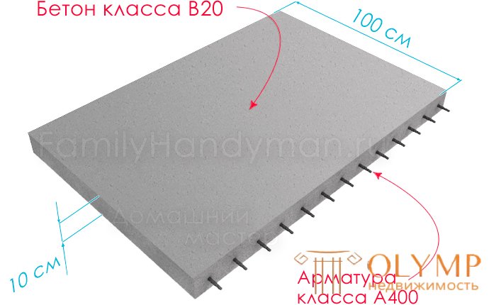
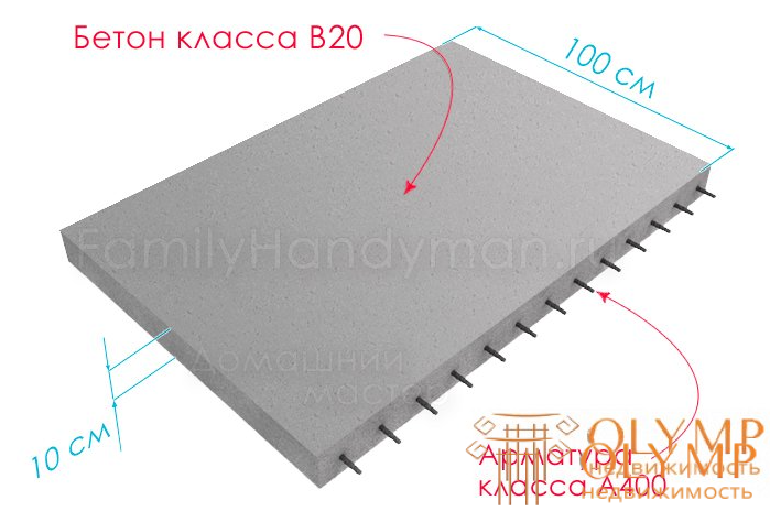
We set the parameters of the plate: height h = 10 cm; width b = 100 cm. This convention will help determine the value of 1 calculated meter. Based on this, in the manufacture of a plate (for example) with a length of 4 and a width of 6 meters, for each of the 6 meters it is necessary to accept the parameters defined for one calculated meter.
So, we have taken the values of height h = 10 cm , width b = 100 cm , as well as the class of concrete B20 and reinforcement A400 .
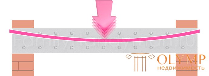
Depending on the type and severity of the walls, as well as on the width of the support of the floor slab on them, the supporting element can be viewed as a hinged supportless beam or the same as a beam with rigid crushing on supports. In this article, the most common case will be considered - a hinged supportless console beam.
The beam may experience a wide variety of loads. Construction mechanics "says" that everything fixed, nailed, glued or otherwise arranged on the floor slab becomes a statistical and at the same time constant load. And everything that moves (that moves in different ways) along the beam becomes a dynamic (usually temporary) load. All this to the fact that in this example we will remove the differences between these types of loads.
The concentrated load is measured in kilogram-forces (kgf or kg) or in Newtons. Distribution load is measured in kilogram-force meter (kgf / m).
The calculation of the floor slab in residential buildings, as a rule, is aimed at determining the distribution load q1 = 400 kg / m². The weight of a plate with a height of 100 mm will add to this type about 250 kg / m². And the screed and fair coating (take the ceramic tile) will add an additional 100 kg / m² here.
In the above distribution load, most of the loads that are related to floors in residential buildings are taken into account. However, this in no way means that the design calculation taking into account more significant loads cannot take place. Not at all, just in our case, the values taken are averaged. At the same time, in any case, we will back up and multiply the final load value by the so-called safety coefficient γ = 1.2 .
q = (400 + 250 + 100) 1.2 = 900 kg / m²
Since our calculations are based on a slab with a width of 1 m, the load, which is distributional, can be considered as flat (working on the slab along the “y” axis and measured in kg / m).
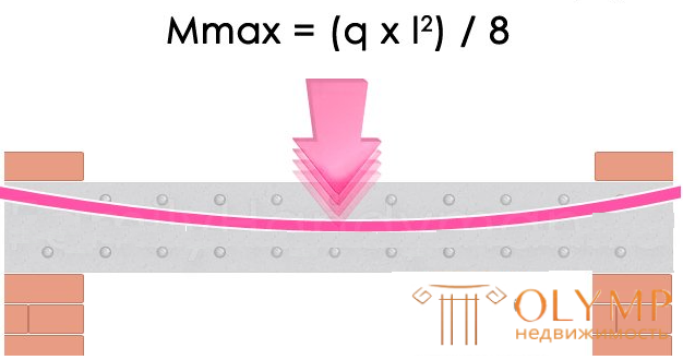
The maximum bending moment of the slab resting on two walls is located along its center:

For span l = 4 m, Mmax = (900x4²) / 8 = 1800 kg · m
According to SNiP 52-01-2003 and SP 52-101-2003 , the basis for calculating w / w elements is the following information:
To eliminate the possibility of formation of the plastic hinge effect (where the value of the bending moment is distant from zero, as a result of which the structure collapses) the ratio ξ of the compressed concrete zone “y” to the distance from the center of gravity of the reinforcement to the top of the beam h0 , ξ = у / h o (6.1) must exceed the limit value ξR .
The following formula is used to determine the limit value:

Formula (6.2) is empirical (based on direct observation) and derived in the design of reinforced concrete structures. The value of Rs is the reinforcement resistance measured in MPa (millipascals). At the same time, this stage of work allows the use of table 1.
The value aR denotes the distance from the center point of the reinforcement cross section to the lower level of the beam. With an increase in this distance (its minimum value should not be not less than the diameter of the reinforcement itself and not less than 10 mm) the adhesion of the reinforcement to the concrete increases. However, along with this decreases the useful value of h0 .
Table 1. Boundary values of the relative height of the compressed zone of concrete:
| Reinforcement class | A240 | A300 | A400 | A500 | B500 |
| ΞR value | 0.612 | 0.577 | 0.531 | 0.493 | 0.502 |
| AR value | 0.425 | 0.411 | 0.390 | 0.372 | 0.376 |
If the calculations are carried out by insufficiently qualified designers (roughly speaking, not by professionals) for the purpose of caution, it is recommended to underestimate the value of the compressed zone ξR by 1.5 times.
In our case, a = 200 mm.
If ξ ≤ ξR or there is no reinforcement in the compressed zone, the following formula is used to test the strength of concrete:

The meaning of this formula is the following: since any moment can be represented as a force working with a shoulder, the above condition should be applied to concrete.
For the same ξ ≤ ξR , the following formula is used to test the strength of rectangular sections with single reinforcement:
The meaning of this formula is as follows: according to the calculation, the reinforcement must withstand a load equal to that which the concrete can withstand. Since both the former and the latter experience an action of the same force with a similar shoulder.
This design scheme is not unique, the calculation can be made relative to the center of gravity of the reduced section. But it is worth noting that reinforced concrete is a composite (artificially created solid material with a heterogeneous composition) material , due to which its calculation by limiting stresses (when squeezed or stretched) arising in the cross section of a reinforced concrete beam is a rather difficult task. At the same time, reinforced concrete is not alone in this. The variation in strength characteristics occurs in structural materials such as steel, aluminum, etc. This can also include wood, brick, as well as polymer composite materials.
To determine the height of the compressed zone of concrete in the absence of reinforcement in it, the following formula is used:

To be able to determine the reinforcement section, it is necessary to determine the am factor:

If am then the need for reinforcement in the compressed zone is completely eliminated. In turn, to determine aR table 1 is used.
In the absence of reinforcement in the compressed zone, the following formula is used to determine the reinforcement cross-section:

Please note that the calculation will be carried out on the example of a reinforced concrete flat plate, which is located on supports of the hinge type and is subjected to a uniform distribution load.
According to SNiP 2.03.01-84 "Concrete and reinforced concrete structures", the calculated resistance to tensile forces for reinforcement class A400 is Rs = 3600 kgf / cm² (355 MPa). According to the same SNiP , the design resistance to compressive loads for concrete of class B20 is Rb = 117 kgf / cm² (11.5 MPa). Other parameters and loads required for the calculation with respect to the slab, we have previously defined.
Using the formula (6.6) we determine the value of the coefficient am : am = 1800 / (1 · 0.08² · 11,70000) = 0.24038
Note: in order to comply with the dimension, the value of the calculated resistance was given in kg / m².
According to Table 1, the value obtained as a result of the calculations is below the limit (0.24038 <0.39), from this it follows that such circumstances do not require the presence of reinforcement in the compressed zone. It turns out that according to the formula (6.8) the required cross-sectional area of the reinforcement: As = 117 · 100 · 8 (1-√‾ (1-2 · 0.24038)) / 3600 = 7.265 cm².
Note: in order to simplify the calculation, the cross-section values were presented in centimeters, and the calculated resistance values in kg / cm².
It turns out that for the reinforcement of one running meter you will need 5 rods Ø14 mm and with a cell of 200 mm. Together with this, the cross-sectional area of the reinforcement will be equal to 7.69 cm². It is also worth noting that table 2 can be used to increase the productivity of reinforcement selection:
| Diameter, mm | Cross-sectional area, cm², with the number of rods | |||||||||
| one | 2 | 3 | four | five | 6 | 7 | eight | 9 | Mass 1 am m, kg | |
| Wire and rod fittings | ||||||||||
| 3 | 0.071 | 0.14 | 0.21 | 0.28 | 0.35 | 0.42 | 0.49 | 0.57 | 0.64 | 0.052 |
| four | 0.126 | 0.25 | 0.38 | 0.5 | 0.63 | 0.76 | 0.88 | 1.01 | 1.13 | 0.092 |
| five | 0.196 | 0.39 | 0.59 | 0.79 | 0.98 | 1.18 | 1.37 | 1.57 | 1.77 | 0.144 |
| 6 | 0.283 | 0.57 | 0.85 | 1.13 | 1.42 | 1.7 | 1.98 | 2.26 | 2.55 | 0,222 |
| 7 | 0.385 | 0.77 | 1.15 | 1.54 | 1.92 | 2.31 | 2.69 | 3.08 | 3.46 | 0,302 |
| eight | 0.503 | 1.01 | 1.51 | 2.01 | 2.51 | 3.02 | 3.52 | 4.02 | 4.53 | 0.395 |
| 9 | 0.636 | 1.27 | 1.91 | 2.54 | 3.18 | 3.82 | 4.45 | 5.09 | 5.72 | 0.499 |
| ten | 0.785 | 1.57 | 2.36 | 3.14 | 3.93 | 4.74 | 5.5 | 9.28 | 7.07 | 0.617 |
| 12 | 1,313 | 2.26 | 3.39 | 4.52 | 5.65 | 6.79 | 7.92 | 9.05 | 10.18 | 0.888 |
| 14 | 1.539 | 3.08 | 4.62 | 6.16 | 7,69 | 9.23 | 10.77 | 12.31 | 13.85 | 1,208 |
| sixteen | 2,011 | 4.02 | 6.03 | 8.04 | 10.05 | 12.06 | 14.07 | 16.08 | 18.1 | 1.578 |
| 18 | 2.545 | 5.09 | 7.63 | 10.18 | 12.72 | 15.27 | 17.81 | 20.36 | 22.90 | 1,998 |
| 20 | 3.142 | 6.28 | 9.41 | 12.56 | 15.71 | 18.85 | 21.99 | 25.14 | 28.28 | 2.466 |
| 22 | 3,801 | 7,6 | 11.4 | 15.2 | 19.0 | 22.81 | 26.61 | 30.41 | 34.21 | 2,984 |
| 25 | 4,909 | 9.82 | 14.73 | 19.63 | 24.54 | 29.45 | 34.36 | 39.27 | 44.13 | 3,853 |
| 28 | 6.158 | 12.32 | 18.47 | 24.63 | 30.79 | 36.95 | 43.1 | 49.26 | 55.42 | 4,834 |
| 32 | 8,042 | 16.08 | 24.13 | 32.17 | 40.21 | 48.25 | 56.3 | 64.34 | 72.38 | 6.313 |
| 36 | 10.18 | 20.36 | 30,54 | 40.72 | 50.9 | 61.08 | 71.26 | 81.44 | 91.62 | 7.99 |
| 40 | 12.56 | 25.12 | 37.68 | 50.24 | 62,8 | 75.36 | 87.92 | 100.48 | 113.04 | 9.87 |
| 45 | 15,904 | 31.81 | 47.71 | 63.62 | 79.52 | 95.42 | 111.33 | 127.23 | 143.13 | 12.49 |
| 50 | 19,635 | 39.27 | 58.91 | 78.54 | 98.18 | 117.81 | 137.45 | 157.08 | 176.72 | 15.41 |
| 55 | 23.76 | 47.52 | 71.28 | 95.04 | 118,8 | 142.56 | 166.32 | 190.08 | 213.84 | 18.65 |
| 60 | 28.27 | 56,54 | 84,81 | 113.08 | 141.35 | 169.62 | 197.89 | 226.16 | 254.43 | 22.19 |
| 70 | 38.48 | 76.96 | 115.44 | 153.92 | 192.4 | 230.88 | 269.36 | 307.84 | 346.32 | 30.32 |
| 80 | 50.27 | 100.55 | 150.81 | 201.08 | 251.35 | 301.62 | 351.9 | 402.15 | 452.43 | 39.46 |
| Seven-wire ropes of class K-7 | ||||||||||
| 4.5 | 0.127 | 0.25 | 0.38 | 0.51 | 0.64 | 0.76 | 0.89 | 1.01 | 1.14 | 0,102 |
| 6 | 0,226 | 0.45 | 0.68 | 0.9 | 1.13 | 1.36 | 1.58 | 1.81 | 2.03 | 0.181 |
| 7.5 | 0.354 | 0.71 | 1.06 | 1.41 | 1.77 | 2.12 | 2.48 | 2.83 | 3.18 | 0.283 |
| 9 | 0,509 | 1.02 | 1.53 | 2.04 | 2.54 | 3.05 | 3.56 | 4.07 | 4.58 | 0.407 |
| 12 | 0.908 | 1.82 | 2.72 | 3.63 | 4.54 | 5.45 | 6.35 | 7.26 | 8.17 | 0.724 |
| 15 | 1,415 | 2.83 | 4.24 | 5.66 | 7.07 | 8.49 | 9.9 | 11.32 | 12.73 | 1,132 |
The reinforcement can also be used 7 rods Ø12 mm with a cell of 140 mm or 10 rods of a larger diameter Ø10 mm with a cell of 100 mm.
Using the formula (6.5) we give an assessment of the strength of concrete: y = 3600 · 7.69 / (117 · 100) = 2.366 cm
ξ = 2.366 / 8 = 0.29575 - the obtained value is below the limit 0.531 and according to the formula (6.1), as well as table 1, below the recommended 0.531 / 1.5 = 0.354 which satisfies the necessary requirements.
It turns out that everything meets the necessary requirements.
Increasing the class of concrete to B25 reduces the amount of reinforcement required, since for B25 Rb = 148 kgf / cm² (14.5 MPa).
It follows from this that for the reinforcement of 1 running meter of the slab, only 5 rods with a diameter of 14 mm with a pitch of 200 mm will be needed (further selection of the section is allowed). It is also worth noting that in order to meet the requirements for the maximum allowable deflection, the height of the plate is overestimated to 130-140 mm, while the reinforcement section is 4-5 rods Ø16 mm.
Что бы оставить комментарий войдите
Комментарии (0)