
3.14. Reinforced concrete elements are calculated on the strength of the action of bending moments, shear forces, longitudinal forces, torque, and the local action of the load (local compression, pushing, tearing).
CALCULATION OF REINFORCED CONCRETE ELEMENTS FOR THE EFFECT OF BENDING MOMENTS
General provisions
3.15. The calculation of the strength of reinforced concrete elements on the action of bending moments should be made for sections that are normal to their longitudinal axis.
The calculation of the normal sections of the bent elements should be made on the basis of the nonlinear deformation model in accordance with PP.3.72 - 3.76, taking N = 0.
Calculation of rectangular, T-shaped and I-beam sections with reinforcement located perpendicular to the plane of the bending of the faces of the element, under the action of the moment in the plane of symmetry of the section, is allowed to be made according to the limiting efforts according to paragraphs.3.17-3.27.
The calculation of elements with such cross sections for the effect of oblique bending in some cases is also allowed to be carried out by limiting efforts in accordance with paragraphs.3.28 and 3.29.
3.16. For reinforced concrete elements, in which the ultimate strength of the bending moment is less than the moment of formation of cracks (sections 4.5-4.8), the cross-sectional area of the longitudinal tensile reinforcement should be increased compared to the required strength calculation by at least 15% or should satisfy the calculation on the strength of the effect of the moment of formation of cracks.
3.17. The calculation of the strength of normal sections should be made depending on the ratio between the relative height of the compressed zone of concrete  , determined from the corresponding equilibrium conditions, and the value of the boundary relative height of the compressed zone ξ R at which the limiting state of the element occurs simultaneously with the achievement in the tension reinforcement of a voltage equal to the calculated resistance Rs.
The value of ξ R is determined by the formula
 (3.15)
where Rs - in MPa or table. 3.2.
Table 3.2
Reinforcement class | A240 | A300 | A400 | A500 | B500 |
Ξ R value | 0.612 | 0.577 | 0.531 | 0.493 | 0.502 |
AR value | 0.425 | 0.411 | 0.390 | 0.372 | 0.376 |
Rectangular sections
3.18. The calculation of rectangular sections (Fig.3.3) is performed as follows depending on the height of the compressed zone
 (3.16)
a) at  - of condition
 (3.17)
b) at  - of condition
 (3.18)
Where  or see tab. 3.2.
The right side of condition (3.18), if necessary, can be slightly increased by replacing the value of aR by (0.7 aR + 0.3 am ), where am = ξ (1 - 0.5 ξ ), and taking here ξ no more than 1.
If x ≤ 0, the strength is checked from the condition
M ≤ RsAs ( h0 - a ') (3.19)
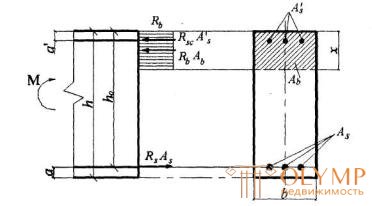
Damn.3.3. Diagram of stresses and stress diagram in transverse rectangular cross section of a flexible concrete element
If the height of the compressed zone x less than 2 a ', calculated without taking into account compressed reinforcement ( As = 0,0) , is checked condition (3.19), where x / 2 is substituted for a ' .
3.19. Flexural elements are recommended to be designed to ensure that the condition  . Non-fulfillment of this condition can be allowed only in cases when the cross-sectional area of the tensioned reinforcement is determined on the basis of the limiting conditions of the second group or adopted for constructive reasons.
3.20. The strength test of rectangular sections with single reinforcement is produced:
for x <ξ R ho from the condition
M ≤ RsAs ( h0-0 , 5x) (3.20)
where x is the height of the compressed zone, equal to  ; ξ R - see p.3.17;
for x ≥ ξ R ho from the condition
 (3.21)
where aR - see table. 3.2;
while the carrying capacity can be slightly increased, using the recommendation of paragraph 3.18, b.
3.21. Selection of longitudinal reinforcement produced as follows.
Calculate the value
 . (3.22)
If a t < ar (see Table 3.2), compressed reinforcement is not required by calculation.
In the absence of compressed reinforcement, the cross-sectional area of the stretched reinforcement is determined by the formula
 , (3.23)
If a t > ar , it is required to increase the cross-section or increase the class of concrete, or install compressed reinforcement in accordance with clause 3.2.
3.22. The cross-sectional areas of stretched As and compressed A ' s reinforcement, corresponding to the minimum of their sum, if computed reinforcement is required by calculation (see p.3.21), is determined by the formulas:
 (3.24)
 (3.25)
where ξ R and ar see table. 3.2
If the value of the accepted cross-sectional area of compressed reinforcement As significantly exceeds the value calculated by the formula (3.24), the cross-sectional area of the tensioned reinforcement can be slightly reduced compared to that calculated by the formula (3.25) using the formula
 (3.26)
Where 
In this case, the condition a τ < ar must be satisfied (see Table 3.2).
Branded and I-sections
3.23. The calculation of the sections having a shelf in a compressed zone (T-shaped, I-beam, etc.) is performed depending on the position of the boundary of the compressed zone:
a) if the border passes in the shelf (fig. 3.4, a), i.e. condition is met
 (3.27)
The calculation is made according to PP.3.18 and 3.20 as for a rectangular section of width  ;
;
b) if the boundary passes in the edge (Fig. 3.4, b), i.e. condition (3.27) is not met, the calculation is made from the condition:
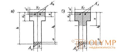
Figure 3.4. The position of the boundary of the compressed zone in the T-section of the flexible concrete element
a-in a stick; b - in the edge
 , (3.28)
where A0 v is the sectional area of the overhangs of the flange, equal to ( b ' f - b ) h' f, while the height of the compressed zone is determined by the formula
 (3 29)
and take no more than ξ R ho (see table. 3.2).
If x> ξ R ho condition (3.28) can be written as
 , (3.30)
where aR - see table. 3.2.
Notes: 1. With a variable height of the shelf overhangs, it is allowed to take the value h ' f equal to the average height of the overhangs.
2. The width of the compressed flange b ' f entered into the calculation should not exceed the values specified in clause 3.26.
3.24. The required cross-sectional area of compressed reinforcement is determined by the formula
 (3.31)
where aR - see table. 3.2; A0 v = ( b ' f - b ) h' f
In this case, the condition h ′ f ≤ ξ R ho must be satisfied. In the case where h ′ f > ξ R ho , the cross-sectional area of the compressed reinforcement is determined as for a rectangular section of width b = b ′ f by formula (3.24).
3.25. The required cross-sectional area of tensioned reinforcement is determined as follows:
a) if the boundary of the compressed zone passes in the shelf, i.e. observed condition:
 (3.32)
the cross-sectional area of the reinforcement is determined as for a rectangular cross-section with a width of b ' f according to p.3.21 and p.3.22;
b) if the boundary of the compressed zone passes in the edge, i.e. condition (3.32) is not met, the cross-sectional area of the tensioned reinforcement is determined by the formula
 (3.33)
Where  . (3.34)
In this case, the condition a t ≤ ar must be satisfied (see Table 3.2).
3.26. The value b ' f entered into the calculation is taken from the condition that the width of the overhang of the shelf in each direction from the rib should be no more than 1/6 of the span of the element and no more:
a) in the presence of transverse ribs or when h ' f ≥ 0.1 h - 1/2 of the clear distance between the longitudinal edges;
b) in the absence of transverse edges (or at distances between them greater than the distance between the longitudinal edges) and at h ' f <0.1 h - 6 h ' f ;
c) with console shelf overhangs
when h ' f ≥ 0.1 h - 6 h ' f ,
at 0.05 h ≤ h ′ f <0.1 h - 3 h ′ f ;
when h ' f < 0.05 h - overhangs do not take into account.
Calculation examples
Rectangular sections
Example 2. Given : cross section of size b = 300 mm, h = 600 mm; a = 40 mm; bending moment, taking into account short-term loads M = 200 kNm; concrete class B15 ( Rb = 8.5 MPa); reinforcement class A300 ( Rs = 270 MPa).
It is required to determine the cross-sectional area of the longitudinal reinforcement.
Calculation .. ho = 600 - 40 = 560 mm. Selection of longitudinal reinforcement produced in accordance with p.3.21. By the formula (3.22) we calculate the value of am

According to the table. 3.2. we find ar = 0.41. Since am = 0.25 < ar , compressed reinforcement is not required by calculation.
The required cross-sectional area of tensioned reinforcement is determined by the formula (3.23)

We take 2Æ28 + 1Æ25 ( As = 1598 mm2).
Example 3 Given : cross-section with dimensions b = 300 mm, h = 800 mm; a = 70 mm; tensile reinforcement A400 ( Rs = 355 MPa); its cross-sectional area is As = 2945 mm2 (6Æ25); concrete class B25 ( Rb = 14.5 MPa); bending moment M = 550 kNm.
Required to check the strength of the section.
Calculation .. ho = 800 - 70 = 730. We test the strength according to p. 3.20:
Determine the value of x:

According to the table. 3.2 we find ξ R = 0,531 . Because  ,
,
check condition (3.20):
RsAs ( ho- 0, 5x) = 355 · 2945 · (730 - 0.5 · 240) = 636.8 · 106 N mm = 636.8 kNm> M = 550 kNm,
those. cross section strength provided.
Example 4. Given : section b = 300 mm, h = 800 mm; a = 50 mm; reinforcement class A400 ( Rs = Rsc = 355 MPa); bending moment M = 780 kNm; concrete class B15 ( Rb = 8.5 MPa).
It is required to determine the cross-sectional area of the longitudinal reinforcement.
Calculation .. ho = h - a = 800-50 = 750 mm. The required area of the longitudinal reinforcement is determined according to p.3.21. By the formula (3.22) we find the value of am :

Since am = 0.544> ar = 0.39 (see Table 3.2), for a given section size and concrete class, compressed reinforcement is necessary.
Taking a ' = 30 mm and ξ R = 0,531 (see tab. 3.2), according to the formulas (3.24) and (3.25) we determine the required cross-sectional area of compressed and stretched reinforcement:


We accept As = 942 mm2 (3Æ20); As = 4021 mm2 (5Æ32).
Example 5. Given : section with dimensions b = 300 mm, h = 700 mm; a = 50 mm; a ' = 30 mm; concrete class B30 ( Rb = 17 MPa); reinforcement A400 ( Rs = Rsc = 355 MPa); the cross-sectional area of compressed reinforcement As = 942 mm2 (3Æ20); bending moment M = 580 kN m.
It is required to determine the cross-sectional area of the tensioned reinforcement.
Calculation .. ho = 700 - 50 = 650 mm. The calculation is made taking into account the presence of compressed reinforcement in accordance with p.3.22.
Calculate the value of am :

Since am = 0.173 < ar = 0.39 (see table. 3.2), the required area of tensile reinforcement is determined by the formula (3.26)

Accepted 3Æ36 ( A s = 3054 mm2).
Example 6. Given : section with dimensions b = 300 mm, h = 700 mm; a = 70 mm; a '= 30 mm; concrete class B20 ( Rb = 11.5 MPa); reinforcement class A400 ( Rs = Rsc = 355 MPa); cross-sectional area of tensile reinforcement As = 4826 mm2 (6Æ32), compressed - A ' s = 339 mm2 (3Æ12); bending moment M = 630 kN m
Required to check the strength of the section.
Payment. ho = 700 - 70 = 630 mm. Check the strength of the section produced in accordance with p.3.18.
According to the formula (3.16) determine the height of the compressed zone x:

According to the table. 3.2 we find ξ R = 0,531 and ar = 0,39. Because  , the strength of the section is checked from the condition (3.18):
 ,
,
those. strength according to this condition is not provided. We specify the right-hand side of condition (3.18) by replacing the value of ar by (0.7 ar + 0.3 am ), where
am = ξ (1 - 0.5 ξ ) = 0.733 (1- 0.5 · 0.733) = 0.464:
(0.7 · 0.39 + 0.3 · 0.464) 11.5 · 300 · 6302 + 355 · 339 · 600 = 636.6 · 106 N · mm = 636.6 kN · m> M = 630 kNm, those. strength provided.
Branded and I-sections
Example 7 Given : cross section with dimensions b ' f = 1500 mm, h' f = 50 mm,
b = 200 mm, h = 400 mm; a = 80 mm; concrete of class B25 ( Rb = 14.5 MPa), reinforcement of class A400 ( Rs = 355 MPa); bending moment M = 260 kNm.
It is required to determine the cross-sectional area of the longitudinal reinforcement.
Payment. ho = 400 - 80 = 320 mm. The calculation is made according to p.3.25 on the assumption that compressed reinforcement is not required by calculation.
Check the condition (3.32), taking As = 0:
 those. the boundary of the compressed zone is held in the shelf, and the calculation is made as for a rectangular section of width b = b ' f = 1500 mm according to p.3.21.
Calculate the value
 (see table 3.2)
those. compressed reinforcement is really by calculation not required.
The cross-sectional area of tensile reinforcement is calculated by the formula (3.22)

We take 4Æ28 ( As = 2463 mm2).
Example 8 Given : section with dimensions b ' f = 400 mm, h' f = 120 mm, b = 200 mm, h = 600 mm; a = 65 mm; concrete class B15 ( Rb = 8.5 MPa); reinforcement class A400 ( Rs = 355 MPa); bending moment M = 270 kNm.
It is required to determine the cross-sectional area of the tensioned reinforcement.
Payment. ho = 600 - 65 = 535 mm. The calculation is made according to p.3.25 on the assumption that compressed reinforcement is not required by calculation.
Because
Rbb ' f h' f ( ho - 0.5 h ' f ) = 8.5 · 400 · 120 (535 - 0.5 · 120) = 193.8 · 106 N mm = 193.8 kNm> M = 270 kNm
the boundary of the compressed zone passes in the rib and the cross-sectional area of the stretched reinforcement is determined by the formula (3.33), taking the cross-sectional area of the overhangs equal to A0 v = ( b ' f - b ) h' f = (400 - 200) 120 = 24000 mm2. Calculate the value of am when A ' s = 0
 (see table. 3.2),
therefore, compressed reinforcement is not required.

We take 4Æ25 ( As = 1964 mm2).
Example 9. Given : section with dimensions b ' f = 400 mm, h' f = 100 mm, b = 200 mm, h = 600 mm; a = 70 mm, concrete class B25 ( Rb = 14.5 MPa); tensile reinforcement class A400 ( Rs = 355 MPa); its cross-sectional area is As = 1964 mm2 (4Æ25); A ' s = 0,0; bending moment M = 300 kNm.
Required to check the strength of the section.
Payment. ho = 600 - 70 = 530 mm. The strength test is performed in accordance with p.3.23, taking As = 0,0. Since Rs · As = 355 · 1964 = 697220 H > Rb · b ' f · h' f = 14.5 · 400 · 100 = 580000 N, the boundary of the squeezed zone passes in the edge, and the cross section strength is checked from condition (3.28) .
To do this, by the formula (3.29) we determine the height of the compressed zone, taking the area of the overhangs equal to A0 v = ( b ' f - b ) h' f = (400 - 200) · 100 = 20000 mm2:

(where ξ R is found from table. 3.2).
 those. cross section strength provided.
Oblique-bending elements
3.27. Calculation of rectangular, T-shaped, I-beam and L-shaped sections of elements working for oblique bending is allowed to be made, taking the form of a compressed zone according to Figure 3.5; this condition must be met
MX < Rb [ Aweb ( h0 - x 1/3) + Sov, x ] + RscSsx , (3.35)
where MX is the component of the bending moment in the x- axis plane (two mutually perpendicular axes passing through the center of gravity of the section of tensioned reinforcement parallel to the sides of the section are taken for the x and y axes; x- axis is parallel to the edge plane);
Aweb = A b - A0 v ; (3.36)
And b - the cross-sectional area of the compressed zone of concrete, equal to
 (3.37)
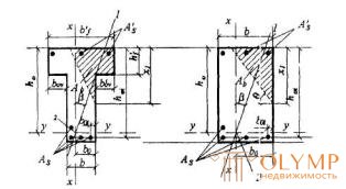
Fig.3.5 Compressed zone shape in cross section of a reinforced concrete element working for oblique bending
a - T-section; b - rectangular section; 1-plane of action of the bending moment; 2- center of gravity of tensioned reinforcement section
A0 v - the area of the most compressed shelf overhang;
x 1 - the size of the compressed zone of concrete on the most compressed side of the section, determined by the formula
 (3.38)
Where 
S0 v, y, S0 v, x - static moments of the area Aov with respect to
x and y axes respectively ;
β is the angle of inclination of the plane of action of the bending moment to the x axis , i.e. ctg β = Mx / My ( My is the component of the bending moment in the plane of the y axis);
bо is the distance from the center of gravity of the section of tensioned reinforcement to the most compressed side edge of the rib (side).
When calculating rectangular sections, the values of Aov, S0 v, y, S0 v, x are assumed to be zero.
If A b < Aov or x 1 <0,2 h ' f, the calculation is performed as for a rectangular section of width b = b' f . If the condition is met
 (3.39)
(where b0 v is the width of the least compressed shelf overhang),
calculation is made without oblique bending, i.e. according to the formula PP. 3.18 and 3.23 on the effect of the moment М = Мх , in this case it is necessary to check the condition (3.40), taking x 1 as in the case of oblique bending.
When determining the value of A b according to the formula (3.37), the voltage in the stretched rod closest to the boundary of the compressed zone should not be less than Rs, which is ensured by the observance of the condition
 (3.40)
where ξ R - see table. 3.2;
b0 i and h0 i are the distances from the rod under consideration, respectively, to the most compressed face (side) and to the most compressed face that is normal to the x axis (see Figure 3.5);
b ' ov - the width of the most compressed overhang;
θ is the angle of inclination of the straight line bounding the compressed zone to the y axis; the value of tg θ is determined by the formula

If the condition (3.40) is not met, the section is calculated by successive approximations, replacing in the formula (3.37) for each stretched bar, the value of Rs with stress values equal to
 (MPa), but not more than Rs.
При проектировании конструкций не рекомендуется допускать превышение значения ξ i над ξ R более чем на 20%, при этом можно провести только один повторный расчет с заменой в формуле (3.37) значений Rs для растянутых стержней, для которых ξ i > ξ R , на напряжения, равные
 (3.41)
При пользовании формулой (3.37) за растянутую арматуру площадью As рекомендуется принимать арматуру, располагаемую вблизи растянутой грани, параллельной оси у, а за сжатую арматуру площадью As - арматуру, располагаемую вблизи сжатой грани, параллельно оси у, но по одну наиболее сжатую сторону от оси x : (см. черт.3.5).
Настоящим пунктом можно пользоваться, если выполняется условие:
для прямоугольных, тавровых и Г-образных сечений с полкой в сжатой зоне х 1 < h ;
для двутавровых, тавровых и Г-образных сечений с полкой в растянутой зоне х 1 < h - hf – bov , t tg θ ,
где hf и bov , t - высота и ширина наименее растянутого свеса полки (черт.3.6).
В противном случае расчет производится на основе нелинейной деформационной модели согласно пп.3.72 - 3.76, принимая N = 0.
3.28. Требуемое количество растянутой арматуры при косом изгибе для элементов прямоугольного, таврового и Г-образного сечений с полкой в сжатой зоне рекомендуется определять с помощью графиков на черт.3.7. Для этого ориентировочно задаются положением центра тяжести сечения растянутой арматуры и по графику определяют значения as в зависимости от:
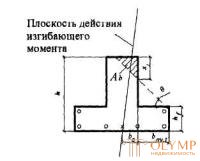
Черт.3.6. Тавровое сечение со сжатой зоной, заходящей в наименее растянутый свес полки


где Ssx и Ssy - статические моменты площади As относительно соответственно оси y и оси х.
Остальные обозначения - см. п.3.27.
Если атх < 0, расчет производится как для прямоугольного сечения, принимая b = b' f .
Если значение as на графике находится по левую сторону от кривой, отвечающей параметру  , подбор арматуры производится без учета косого изгиба, т.е. согласно пп.3.22 и 3.26 на действие момента М = Мх .
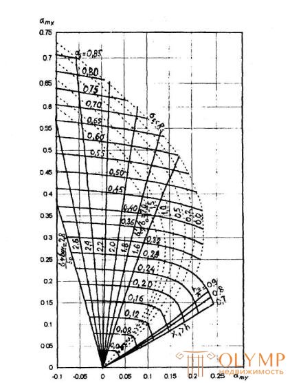
Черт.3.7 . График несущей способности прямоугольного, таврового и Г-образного сечений для элементов, работающих на косой изгиб

Требуемая площадь растянутой арматуры при условии ее работы с полным расчетным сопротивлением определяется по формуле
 (3.42)
где A ov - см. формулу (3.36).
Центр тяжести фактически принятой растянутой арматуры должен отстоять от растянутой грани не дальше, чем принятый в расчете центр тяжести. В противном случае расчет повторяют, принимая новый центр тяжести сечения растянутой арматуры.
Условием работы растянутой арматуры с полным сопротивлением является выполнение условия (3.40). При арматуре класса А400 и ниже условие (3.40) всегда выполняется, если значение as на графике 3.7 находится внутри области, ограниченной осями координат, и кривой, отвечающей параметру b ' ov / bo
Если условие (3.40) не выполняется, следует поставить (увеличить) сжатую арматуру, либо повысить класс бетона, либо увеличить размеры сечения (особенно наиболее сжатого свеса полки).
Значения as на графике не должны находиться между осью amy , и кривой, соответствующей параметру ho / h . В противном случае х 1 становится более h , и расчет тогда следует производить согласно пп.3.72 - 3.76.
Примеры расчета
Пример 10. Дано : железобетонный прогон кровли с уклоном 1:4 (ctg β = 4); сечение и расположение арматуры - по черт.3.8; бетон класса В25 ( Rb =14,5МПа); растянутая арматура класса А400 ( Rs = 355МПа); As = 763 мм2 (3Æ18); A ' s = 0,0; изгибающий момент в вертикальной плоскости M = 82,6 кНм.
Требуется проверить прочность сечения.
Ра с ч е т. Из черт.3.8 следует:
ho = 400-30-(1·30/3)=360 мм; bo = (2·120+1·30)/3=90 мм; b ' ov = bov = (300-150)/2=75 мм;
h' f = 80+20/2=90 мм.
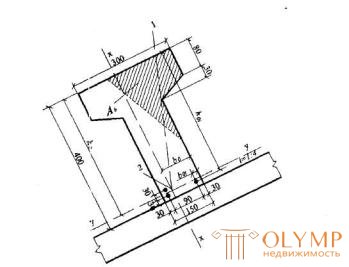
Черт.3.8 К примеру расчета 10
1 -плоскость действия изгибающего момента; 2-центр тяжести сечения растянутой арматуры
По формуле (3.37) определим площадь сжатой зоны бетона А b

Площадь наиболее сжатого свеса полки и статические моменты этой площади относительно х и у соответственно равны:
Aov= b ' ov h ' f = 75·90 = 6750 мм2;
Sov,y = Aov ( b0 + b ' ov /2)=6750(90 + 75/2) = 86,06·104мм3;
Sov,x = Aov ( h0 - h ' f /2) = 6750(360 - 90/2) = 212,6·104мм3.
Так как А b > Aov , расчет продолжаем как для таврового сечения.
Aweb = 18680 - 6750 = 11930 мм2.
Определим по формуле (3.38) размер сжатой зоны х 1. Для этого вычисляем


Проверим условие (3.39):

Therefore, the calculation is continued according to the formulas of oblique bending.
Check condition (3.40) for the least stretched bar. From drawing 3.8, we have boi = 30 mm, hoi = 400 - 30 = 370 mm;

 (see table. 3.2).
Condition (3.40) is not met. We repeat the calculation, replacing the value of Rs for the least-stretched bar with the stress σS determined by the formula (3.41) in formula (3.37), and correcting the values of ho and bо.

Since all rods are of the same diameter, the new values of Ao, ho, and bо will be equal to:

Similarly, we define the values Sov , y, Sov , x, Aweb and x 1:
Sov, y = 6750 · (91.1 + 75/2) = 86.8 · 104mm3;
Sov, x = 6750 · (359.8 - 90/2) = 212.5 · 104 mm3;
Aweb = 18338 - 6750 = 11588 mm2;


Check the strength of the section from the condition (3.35), taking Ssx = 0 and

Rb [ Aweb ( h0 - x 1/3) + Sov, x ] = 14.5 [11588 (359.8-173.1 / 3) + 212.5 · 104] = 81.57 · 106 N · mm> Mx = 80.1 · 106 N · mm
those. cross section strength provided.
Example 11. According to Example 10, it is necessary to select the area of tensioned reinforcement at a moment in the vertical plane M = 64 kNm.
Payment. The components of the bending moment in the plane of the axes y and x are equal to:

Mx = My ctg β = 15.52 · 4 = 62.1 kNm.
Determine the required amount of reinforcement in accordance with p. 3.28.
Taking the values of Rb, ho, Sov , x and Sov , y from example 10 with Ssy = Ssx = 0, we find the values of a to and amy :


Since atx> 0, the calculation is continued for the T-section.
Since the point with coordinates atx = 0.185 and amy = 0.072 on the chart in Figure 3.7 is located on the right side of the curve corresponding to the parameter  , and on the left side of the curve corresponding to the parameter b ' ov / bov = 75/90 = 0.83, the calculation is continued taking into account oblique bending and the total design resistance of the reinforcement, i.e. condition (3.40) is satisfied.
On the graph, the coordinates atx = 0.185 and amy = 0.072 correspond to the value as = 0.20. Then, according to the formula (3.42), the cross-sectional area of the tensioned reinforcement will be equal to
A s = ( as bo ho + Aov ) Rb / Rs = (0.2 · 90 · 360 + 6750) 14.5 / 355 = 540.4 mm2.
The rods are taken 3Æ16 ( A s = 603 mm2) and arranged as shown in Fig. 3.8.
CALCULATION OF REINFORCED CONCRETE ELEMENTS UNDER THE ACTION OF TRANSVERSE FORCES
3.29. The calculation of elements under the action of transverse forces should ensure the strength of:
- along the strip between the inclined sections according to p. 3.30;
- on the effect of a transverse force on an oblique section according to paragraphs.3.31– 3.42;
- on the effect of the moment on the oblique section according to PP.3.43-3.48.
Calculation of reinforced concrete elements in the strip between the inclined sections
3.30. The calculation of the bent elements on the concrete strip between the inclined sections produced from the condition
Q <0.3 Rbbho , (3.43)
where Q is the transverse force in the normal section, taken at a distance from the support not less than ho .
Calculation of reinforced concrete elements on the inclined sections on the action of transverse forces
Constant height elements reinforced with collars normal to the element axis
3.31. The calculation of the bent elements of the oblique section (Fig. 3.9) is made from the condition
Q <Qb + Qsw , (3.44)
where Q is the transverse force in the inclined section with the projection length c from external forces located on one side of the considered inclined section; with a vertical load applied to the upper face of the element, the value of Q is taken in the normal section, passing at a distance from the support; at the same time, it is necessary to take into account the possibility of the absence of a temporary load on the support section of length s ;
Qb is the shear force perceived by the concrete in the inclined section;
Qsw is the transverse force perceived by the clamps in an inclined section.
The transverse force Qb is determined by the formula
 (3.45)
Where
 (3.46)
The value of Qb is not more than 2.5 Rbtbho and not less than 0.5 Rbtbho.
The value of c is determined according to p.
Force Qsw is determined by the formula
Qsw = 0.75 qsw co , (3.47)
where qsw is the force in the clamps per unit length of the element, equal to
 (3.48)
co is the length of the projection of the oblique crack, taken equal to c, but not more than 2 ho .
Clamps are taken into account if the condition is met
qsw > 0.25 Rbtb (3.49)
It is possible not to fulfill this condition if in the formula (3.46) such a reduced Rbtb value is taken into account , at which the condition (3.49) turns into equality, i.e. take 
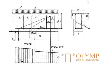
Figure 3.9. The scheme of efforts in the inclined section of elements with clamps when calculating it on the action of transverse force
3.32. When checking, conditions (3.44) are generally set by a number of inclined sections for different values of с, not exceeding the distance from the support to the section with the maximum bending moment and not more than 3 ho
When acting on an element of concentrated forces, the values of с are assumed to be equal to the distances from the support to the points of application of these forces (Fig.3.10), as well as  but not less than h0, if this value is less than the distance from the support to the 1st load.
When calculating an element for the action of a uniformly distributed load q, the disadvantageous value c is taken equal to  and if so
  or
or  should be taken
  where the value of q 1 is determined as follows:
a) if there is a continuous uniformly distributed load q, q 1 = q;
b) if the load q includes a temporary load, which is reduced to a moment-equivalent uniformly distributed load qv (i.e., when the plot of moments M from the calculated load qv always bends around the plot M from any actual temporary load), q 1 = q - 0.5 qv.
Moreover, in condition (3.44), the value of Q is taken equal to Qmax - q 1 s , where Qmax is the transverse force in the support section.
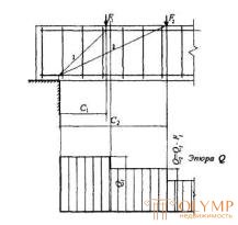
Figure 3.10 . The location of the calculated inclined sections with concentrated forces
1 is an inclined section checked for the action of a transverse force Q 1 ; 2 - the same force Q 2
3.33. The required intensity of the clamps, expressed in terms of qsw (see p.3.31), is determined as follows:
a) when an element is concentrated on forces concentrated at distances from i from the support, for each i- th inclined section with a projection length C i not exceeding the distance to the section with the maximum bending moment, the value qsw ( i) is determined as follows depending on coefficient а i = с i / ho, taken no more than 3:
if a
 (3.50)
if a
 (3.51)
where a0 i - the smaller of the values of a i and 2;
Qi is the transverse force in the ith normal section, located at a distance from i from the support;
the highest value of qsw is finally accepted ,
b) when an element is applied only to a uniformly distributed load q, the required intensity of the clamps qsw is determined depending on  in the following way:
if Qbi ≥ 2 Mb / ho - Qmax
 ; (3.52)
if Qbi < 2 Mb / ho - Qmax .
 ; (3.53)
moreover , if Qbl < Rbtbho,
 , (3.54)
where Mb , see p.3.31; q1 - see p.3.32.
If the obtained value of qsw does not satisfy condition (3.49), it should be calculated by the formula
 (3.55)
and take at least  .
.
3.34. When reducing the intensity of the clamps from the support to the span from qsw1 to qsw2 (for example, increasing the pitch of the clamps), you should check condition (3.44) for values exceeding l1 - the length of the section with the intensity of clamps qsw1 (Fig. 3.11). The value of Qsw is assumed to be:
if c < 2 ho + l1 ,
Qsw = 0.75 [ qsw1c o- ( qsw1 - qsw2 ) ( c - l1 )]; (3.56)
if c> 2 ho + l1 ,
Qsw = 1,5 qsw2ho, (3.57)
co- cm p.3.31.
When a uniformly distributed load is applied to an element, the length of the section with the intensity of clamps qsw1 is assumed to be no less than the value l1 , determined depending on Δ qsw = 0.75 ( qsw1 - qsw2 ) as follows:
- if Δ qsw < q1,
 (3.58)
Where  but not more than 3 h
in this case, if 
- if Δ qsw ≥ q1
 (3.59)
here M b , c0- cm. p.3.31; q1- see p.3.32;
Qb. min = 0,5 Rbtbho
If the condition (3.49) is not fulfilled for the value of qsw2 , the length l1 is calculated for the values corrected according to p.  and Qb. min = 2 hoqsw2; the sum ( Qb. min + 1.5 qsw ho ) in formula (3.59) is assumed to be at least the uncorrected value Qb. min
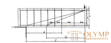
Figure 3.11 . To the calculation of the inclined sections with a change in the intensity of the clamps
3.35. The pitch of the clamps taken into account in the calculation should be no more than the value:
 (3.60)
In addition, the clamps must meet the design requirements given in §5.20 and 5.21.
Elements of variable height with transverse reinforcement
3.36. The calculation of elements with oblique or stretched edges on inclined sections is carried out in accordance with p.3.31, taking as the working height of the cross section the greatest value of ho within the considered oblique section (chart 3.3.12).

Fig.3.12 Beams with a variable section height and inclined face
3.37. For beams without bends with a height that is uniformly increasing from the support to the span, calculated for the action of a uniformly distributed load q , the inclined section is checked from condition (3.44) with an unfavorable value of c equal to
 (3.61)
however, if this value is less than  or,
or,
if a  , the least advantageous value is equal to
 (3.62)
Accepted value with should not exceed  and the length of the section of the beam with a constant value of β.
Here: ho1 is the working height of the support section of the beam;
q1 - see p.3.32;
β is the angle between the compressed and stretched beams edges.
The working height is assumed to be ho = ho1 + c · tg β .
When reducing the intensity of the clamps from qsw1 at the support to qsw2 in the span, it is necessary to check condition (3.44) with values of c exceeding l1 - the length of the element section with the intensity of clamps qsw1 ; the value of Qsw is determined by the formula (3.56) or by the formula (3.57) p.3.34 depending on the fulfillment or non-fulfillment of the condition  .
.
When a concentrated force acts on a beam, the value of с is equal to the distance from the support to the points of application of these forces, and is also determined by the formula (3.62) with q1 = 0 if this value is less than the distance from the support to the 1st load.
3.38. For consoles without bends, a height that is uniformly increasing from the free end to the support (Fig. 13.13), in general, check condition (3.44), specifying by inclined sections with values of c, determined by the formula (3.62) with q1 = 0 and taken no more than from the beginning of the inclined section in the stretched zone to the support. In this case, ho1 and Q take, respectively, the working height and lateral force at the beginning of the inclined section in the stretched zone. In addition, if c > 2 ho1 / (1-2tg β ), check the inclined sections made before support.
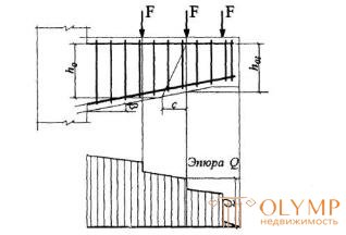
Figure 3.13 . Console height, decreasing from support to free end
Under the action of concentrated forces on the console, the beginning of an inclined section is placed in a stretched zone of normal sections, drawn through the points of application of these forces (see Figure 3.13).
Under the action of a uniformly distributed load or load, linearly increasing to the support, the console is calculated as an element with a constant section height in accordance with p. 3.31 and p. 322, taking the working height hо in the reference section.
Elements reinforced by limb
3.39. The test of the strength of the oblique section on the action of the transverse force for an element with bends is made from the condition (3.44) with the value added to its right side
 (3.63)
where A s, inc is the cross-sectional area of the limb intersecting the inclined crack located at the end of the inclined section with the projection length equal to с, but not more than 2 ho (Figure 3.14);
θ is the angle of inclination of the limb to the longitudinal axis of the element.
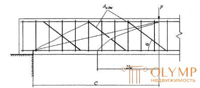
Figure 3.14 . To the definition of the most dangerous inclined crack for elements with bends in the calculation of the effect of lateral force
Values with take equal to the distance from the support to the ends of the limb, as well as to the places of application of concentrated forces; in addition, you should check the inclined sections, ending at a distance of 2 ho from the beginning of the penultimate and last limb plane (Figure 3.15).
3.40. The distance between the support and the end of the limb closest to the support s 1 also between the end of the previous one and the beginning of the next limb s 2 (Fig. 3.16) should be no more than  .
.
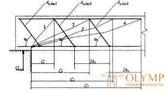
Doc.3.15 . To the definition of inclined sections in the element with limb
1-4 - calculated inclined sections
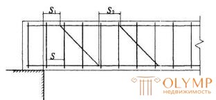
Figure 3.16 . Distances between clamps, support and limb
In addition, the bends should meet the design requirements given in paragraph 5.5.
Elements without shear reinforcement
3.41. The calculation of elements without transverse reinforcement on the effect of transverse force is made from the conditions
a)
Qmax <2.5 Rbtbho (3.64)
where Qmax is the maximum transverse force at the edge of the support;
6)
 (3.65)
where Q is the transverse force at the end of the inclined section, starting from the support; the value of c is taken as not more than max = 3 ho .
For solid flat plates with non-free edges (connected to other elements or having supports) and b > 5 h wide, it is allowed to take Stach = 2,4 ho .
When a concentrated force acts on an element, the values of с are assumed to be equal to the distances from the support to the points of application of these forces (Fig.3.17), but not more than 100 .
When calculating an element for the effect of distributed loads, if the condition
 , (3.66)
condition (3.65) takes the form
Q max <0.5 Rbtbho + 3 hoq 1 (3.67)
(which corresponds to c = 3 ho ) ,
and if condition (3.66) is not met, 
(which corresponds to  ).
).
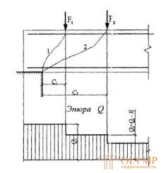
Figure 3.17 . Location of disadvantageous inclined sections in elements without transverse reinforcement
1 is an inclined section, tested for the action of a transverse force Q 1 ; 2 - the same, force Q 2
For the above-mentioned flat plates with non-free side edges, the right-hand side of condition (3.66) is divided by 0.64, and condition (3.67) takes the form
Q max ≤ 0.625 Rbtbho + 2.4 hoq 1. (3.67a)
Here, q 1 is taken under the action of a uniformly distributed load in accordance with p.3.32, and under the action of a continuous load with a linearly varying intensity - equal to the average intensity in the support section of a length equal to a quarter of the span of the beam (plate) or half of the cantilever departure, but not more than 100 .
3.42. For elements with variable section height, when checking condition (3.64), the ho value is taken in the reference section, and when checking condition (3.65), it is taken as the average ho value within an inclined section.
For elements with section height increasing with increasing transverse force, the value with max is taken equal to  , and for flat plates specified in paragraph 3..41, -
where h o1 - working height in the reference section;
β is the angle between the stretched and compressed edges.
When acting on such an element of a distributed load, the value of с in condition (3.65) is taken to be
 (3.68)
but no more than Stakh where q 1 - see p.3.32.
Calculation of reinforced concrete elements for inclined sections on the effect of moments
3.43. The calculation of reinforced concrete elements on the inclined sections on the effect of the moment (Fig.3.18) is made from the condition
M ≤ Ms + M sw, (3.69)
где М - момент в наклонном сечении с длиной проекции с на продольную ось элемента, определяемый от всех внешних сил, расположенных по одну сторону от рассматриваемого наклонного сечения, относительно конца наклонного сечения (точка 0), противоположного концу, у которого располагается проверяемая продольная арматура, испытывающая растяжение от момента в наклонном сечении (черт.3.19)
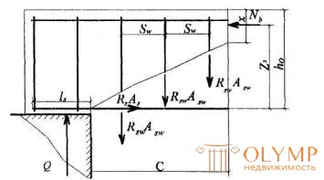
Черт.3.18 . Схема усилий в наклонном сечении при расчете его по изгибающему моменту
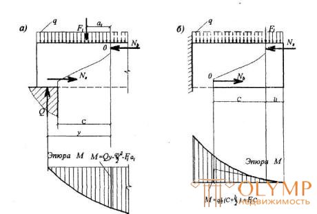
Черт.3.19 . Определение расчетного значения момента при расчете наклонного сечения
а - для свободно опертой балки; б - для консоли
Ms - момент, воспринимаемый продольной арматурой, пересекающей наклонное сечение, относительно противоположного конца наклонного сечения;
M sw - момент, воспринимаемый поперечной арматурой, пересекающей наклонное сечение, относительно противоположного конца наклонного сечения (точка 0).
Момент Ms , определяют по формуле
M s = N s· z s, (3.70)
где Ns - усилие в продольной растянутой арматуре, принимаемое равным RsAs , а в зоне анкеровки определяемое согласно п.3.45;
zs - плечо внутренней пары сил, определяемое по формуле
 (где b - ширина сжатой грани);
но при наличии сжатой арматуры принимаемое не менее h o - a ' ; допускается также принимать zs = 0,9 h o.
Момент M sw при поперечной арматуре в виде хомутов, нормальных к продольной оси элемента, определяют по формуле
Msw =0,5 qsw c 2 (3.71)
где qsw определяют по формуле (3.48) п.3.31, а с принимают не более 2 h o .
Если хомуты в пределах длины с меняют свою интенсивность с qsw у начала наклонного сечения на qsw 2 , момент M sw определяют по формуле:
Msw =0,5 qsw 1 c 2 - 0,5( qsw 1 - qsw 2)( c - l 1)2 (3.72)
где l 1 - длина участка с интенсивностью хомутов qsw 1.
Значение с определяют согласно п.3.46.
3.44. Расчет на действие момента производят для наклонных сечений, расположенных в местах обрыва продольной арматуры, а также у грани крайней свободной опоры балок и у свободного конца консолей при отсутствии у продольной арматуры специальных анкеров.
Кроме того, рассчитываются наклонные сечения в местах резкого изменения высоты элемента (например, в подрезках).
3.45. При пересечении наклонного сечения с продольной растянутой арматурой, не имеющей анкеров в пределах зоны анкеровки, усилие Ns определяется по формуле:
 (3.73)
где ls - расстояние от конца арматуры до точки пересечения с ней наклонного сечения;
1ап - длина зоны анкеровки, равная 1ап = λап ds
Where
 (3.74)
Rbond - расчетное сопротивление сцепления арматуры с бетоном, равное
Rbond = η1 η2 Rbt
η1 - коэффициент, учитывающий влияние вида поверхности арматуры и принимаемый равным:
2,5 - для арматуры классов А300, А400, А500;
2,0 - для арматуры класса В500;
1,5 - для арматуры класса А240;
η2 - коэффициент, учитывающий влияние диаметра арматуры и принимаемый равным:
1,0 - при диаметре ds <32 мм,
0,9 - при диаметрах 36 и 40 мм;
а - коэффициент, учитывающий влияние поперечного обжатия бетона и поперечной арматуры и принимаемый равным:
а) для крайних свободных опор,
если 0,25 ≤ σb / Rb ≤ 0,75 - 0,75;
если σb / Rb < 0,25 или σb / Rb > 0,75 - 1,0,
здесь σb = Fsup/Asup;
Fsup, Asup - опорная реакция и площадь опирания балки;
при этом если имеется поперечная арматура, охватывающая без приварки продольную арматуру, коэффициент а делится на величину  (где Asw и s - площадь сечения огибающего хомута и его шаг) и принимается не менее 0,7;
б) для свободных концов консоли - 1,0.
В любом случае коэффициент λап принимается не менее 15, а длина зоны анкеровки 1ап принимается не менее 200 мм.
Для стержней диаметром менее 36 мм значение λап можно принимать по табл.3.3.
В случае приваривания к продольным растянутым стержням поперечной или распределительной арматуры усилие Ns увеличивается на величину
 , (3.75)
принимаемую не более  .
.
Здесь:
nw - количество приваренных стержней по длине ls ;
φ w - коэффициент, принимаемый по табл.3.4;
dw - диаметр припариваемых стержней.
При этом значение Ns принимается не более значения, вычисленного по формуле (3.73) с использованием при определении 1ап коэффициента, а = 0,7.
При устройстве на концах стержней специальных анкеров в виде пластин, шайб, гаек, уголков, высаженных головок и т.п., удовлетворяющих требованиям п.5.35, а также при приварке концов стержней к надежно заанкеренным закладным деталям усилие Ns принимается равным RsAs .
3.46. Для свободно опертых балок невыгоднейшее наклонное сечение начинается от грани опоры и имеет проекцию с , принимаемую не более 2 ho и определяемую следующим образом:
Таблица 3.3
Reinforcement class | Коэффициент а | Относительная длина анкеровки арматуры λ ап = lan / ds при бетоне классов | ||||||||||
AT 10 | B15 | IN 20 | B25 | B30 | В35 | B40 | В45 | B50 | В55 | B60 | ||
А240 | 0.7 | 45 | 33 | 28 | 24 | 22 | nineteen | 18 | 17 | sixteen | 15 | 15 |
0.75 | 48 | 36 | 36 | 26 | 23 | 21 | nineteen | 18 | 17 | sixteen | 15 | |
1.0 | 64 | 48 | 40 | 34 | 31 | 28 | 26 | 24 | 22 | 21 | 20 | |
А300 | 0.7 | 34 | 25 | 21 | 18 | sixteen | 15 | 15 | 15 | 15 | 15 | 15 |
0.75 | 36 | 27 | 23 | nineteen | 18 | sixteen | 15 | 15 | 15 | 15 | 15 | |
1.0 | 48 | 36 | thirty | 26 | 23 | 21 | nineteen | 18 | 17 | sixteen | 15 | |
А400 | 0.7 | 44 | 33 | 28 | 24 | 22 | nineteen | 18 | 17 | sixteen | 15 | 15 |
0.75 | 48 | 36 | thirty | 25 | 23 | 20 | nineteen | 18 | 17 | sixteen | 15 | |
1.0 | 63 | 47 | 39 | 34 | 31 | 27 | 25 | 24 | 22 | 21 | 20 | |
А500 | 0.7 | 54 | 41 | 34 | 29 | 26 | 23 | 22 | 20 | nineteen | 18 | 17 |
0.75 | 58 | 44 | 36 | 31 | 28 | 25 | 23 | 22 | 20 | nineteen | 18 | |
1.0 | 78 | 58 | 48 | 41 | 38 | 33 | 31 | 29 | 27 | 26 | 24 | |
В500 | 0.7 | 65 | 48 | 40 | 35 | 32 | 28 | 26 | 24 | 23 | 21 | 20 |
0.75 | 69 | 52 | 43 | 37 | 34 | thirty | 28 | 26 | 24 | 23 | 22 | |
1.0 | 93 | 69 | 58 | 49 | 45 | 40 | 37 | 35 | 32 | 31 | 29 | |
Note. При расчете с учетом только постоянных и длительных нагрузок значения λ ап следует делить на γ bl - 0,9. | ||||||||||||
Таблица 3.4.
dw | 6 | eight | ten | 12 | 14 |
φ w | 200 | 150 | 120 | 100 | 80 |
а) если на элемент действуют сосредоточенные силы, значения с принимаются равными расстояниям от опоры до точек приложения этих сил, а также равным Q max/ q sw , если это значение меньше расстояния до 1-го груза;
б) если на элемент действует равномерно распределенная нагрузка q, значение с определяется по формуле:
 , (3.76)
здесь qsw - см. формулу (3.48).
Если хомуты в пределах длины с меняют свою интенсивность с qsw 1 у начала наклонного сечения на qsw2, значение с определяется по формуле (3.76) при уменьшении числителя на Δ qswl 1 а знаменателя - на Δ qsw, (где l 1 - длина участка с интенсивностью qsw 1 , Δ qsw 1 = qsw 1- qsw 2)
Для балок с наклонной сжатой гранью при действии равномерно распределенной нагрузки проверяют наклонные сечения со значениями с, равными
 (3.77)
где ho - рабочая высота в опорном сечении;
β - угол наклона сжатой грани к горизонтали.
При растянутой грани, наклоненной под углом β к горизонтали, в этих формулах значение tg β заменяется на sin β .
Для консолей, нагруженных сосредоточенными силами (черт.3.19,б) проверяются наклонные сечения, начинающиеся у мест приложения сосредоточенных сил вблизи свободного конца со значениями с = Q 1/ qsw (где Q 1 - поперечная сила в начале наклонного сечения), но не более l 1 - расстояния от начала наклонного сечения до опоры. При этом, если Q 1/qsw > 2 h o, следует принимать с = l 1. Если такие консоли имеют наклонную сжатую грань, значение Q 1/ qsw заменяется на ( Q 1 - Ns tg β )/ qsw.
Для консолей, нагруженных только равномерно распределенной нагрузкой q, невыгоднейшее сечение заканчивается в опорном сечении и имеет длину проекции
 (3.78)
но не более 2 ho.
В случае, если с < l - lan , расчет наклонного сечения можно не производить.
Здесь: As – площадь сечения арматуры, доводимой до свободного конца; zs - см. п.3.43; lan - см. п.3.45.
При отсутствии поперечной арматуры значение с принимают равным 2 h o , где h o - рабочая высота в конце наклонного сечения.
3.47. Для обеспечения прочности наклонных сечений на действие момента в элементах постоянной высоты с хомутами продольные растянутые стержни, обрываемые в пролете, должны заводиться за точку теоретического обрыва (т.е. за нормальное сечение, в котором внешний момент становится равным предельному моменту М ult без учета обрываемой арматуры, черт.3.20) на длину не менее величины w, определяемой по формуле
 (3.79)
при этом, если 
 , (3.80)
где Q - поперечная сила в нормальном сечении, проходящем через точку теоретического обрыва;
qsw – см. п.3.31;
ds - диаметр обрываемого стержня.
Для балки с наклонной сжатой гранью при tg β ≤ 0,2 величина w принимается равной
w = aho + 5ds , (3.81)
при этом, если а >1,
w = ho (2,2 - 1,2/ а ) + 5 ds , (3.82)
Where 
β - угол наклона грани к горизонтали.
Для балки с наклонной растянутой гранью w определяется аналогично с заменой tg β на sin β .
Для элементов без поперечной арматуры значение w принимают равным 2 h о .
Кроме того, должны быть учтены требования пп.5.32 и 5.33.
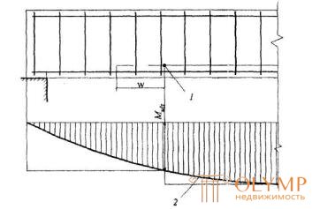
Черт.3.20. Обрыв растянутых стержней в пролете
1- точка теоретического обрыва;2- эпюра М
3.48. Для обеспечения прочности наклонных сечений на действие момента начало отгиба в растянутой зоне должно отстоять от нормального сечения, в котором отгибаемый стержень полностью используется по моменту, не менее, чем на 0,5 ho, а конец отгиба должен быть расположен не ближе того нормального сечения, в котором отгиб не требуется по расчету (черт.3.21).
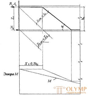
Черт. 3.21. К определению места отгиба продольной растянутой арматуры
Примеры расчета
Расчет наклонных сечений на действие поперечных сил
Пример 12. Дано : ребро ТТ-образной плиты перекрытия с размерами сечения: h = 350 мм, d = 85 мм; а = 35 мм; бетон класса В15 ( Rb = 8,5 МПа, Rbt = 0,75 МПа); ребро армировано плоским каркасом с поперечными стержнями из арматуры класса А400 ( Rsw = 285 МПа) диаметром 8 мм ( Asw = 50,3 мм2) шагом sw - 100 мм; полная равномерно распределенная нагрузка, действующая на ребро, q = 21,9 кН/м; временная эквивалентная нагрузка qv = 18 кН/м; поперечная сила на опоре Qmax = 62 кН.
Требуется проверить прочность наклонных сечений и бетонной полосы между наклонными сечениями.
Payment. ho = h - a = 350-35 = 315 мм.
Прочность бетонной полосы проверим из условия (3.43):
0,3 Rbbh0 = 0,3·8,5·85·315 = 68276 Н > Qmax = 62 кН, т.е. прочность полосы обеспечена.
Прочность наклонного сечения по поперечной силе проверим согласно п.3.31.
По формуле (3.48) определим интенсивность хомутов

Insofar as  i.e. условие (3.49) выполнено, хомуты полностью учитываем и значение М b определяем по формуле (3.46)
М b = 1,5 Rbtbh02 = 1,5·0,75·85·3152 = 9,488·106 Н·мм.
Согласно п.3.32 определим длину проекции невыгоднейшего наклонного сечения с.
q 1 = q - qv/2 = 21,9 - 18/2 = 12,9 кН/м (Н/мм).
Insofar as  , значение с определяем по формуле

Принимаем c o = c = 280,7 мм. Then
Qsw = 0,75 qswco = 0,75·143,3·280,7 = 30168 Н = 30,17 кН.

Q = Q max – q 1 c = 62 - 12,9·0,28 = 58,4 кН.
Проверяем условие (3.44)
Qb + Qsw = 33,8 + 30,17 = 63,97 Н > Q = 58,4 кН,
those. прочность наклонных сечений обеспечена.
Проверим требование п.3.35:

those. требование выполнено. Условия п.5.21 sw < hо /2= 315/2 = 157 мм и sw < 300 мм также выполнены.
Пример 13 . Дано : свободно опертая балка перекрытия с размерами сечения: b = 200 мм, h = 400 мм; ho = 370 мм; бетон класса В25 ( Rbt = 1,05 МПа); хомуты двухветвевые диаметром 8 мм ( Asw = 101мм2) с шагом sw= 150 мм; арматура класса А240 ( Rsw = 170 МПа); временная эквивалентная по моменту нагрузка qv = 36 кН/м, постоянная нагрузка qg = 14 кН/м; поперечная сила на опоре Qmax = 137,5 кН.
Требуется проверить прочность наклонных сечений.
Payment. Прочность наклонных сечений проверяем согласно п.3.31. По формуле (3.48) определим интенсивность хомутов

Insofar as  i.e. условие (3.49) выполняется, хомуты учитываем полностью и значение М b определяем по формуле (3.46)
М b = 1,5 Rbtbhо2 = 1,5·1,05·200·3702 = 4,312·107 Н·мм.
Согласно п.3.32 определяем длину проекции невыгоднейшего наклонного сечения:
q 1 = qg + 0,5 qv = 14 + 0,5·36 = 32 кН/м (Н/мм).
Insofar as

значение с принимаем равным 1161 мм > 2 h0 = 740 мм. Тогда с o = 2 h0 = 740 мм и Qsw = 0,75 q sw c o = 0,75·114,5·740 = 63548 Н = 63,55 кН;

Q = Q max – q 1 c = 137,5 - 32·1,161 = 100,35 кН.
Проверяем условие (3.44)
Qb + Qsw = 37,14 + 63,55 = 100,69 кН > Q = 100,35 кН,
those. прочность наклонных сечений обеспечена.
Пример 14. Дано : свободно опертая балка перекрытия пролетом l = 5,5 м; полная равномерно распределенная нагрузка на балку q = 50 кН/м; временная эквивалентная нагрузка qv = 36 кН/м; размеры поперечного сечения b = 200 мм, h = 400 мм; ho = 370 мм; бетон класса В15 ( Rbt = 0,75 МПа); хомуты из арматуры класса А240 ( Rsw =170 МПа).
Требуется определить диаметр и шаг хомутов у опоры, а также выяснить, на каком расстоянии и как может быть увеличен шаг хомутов.
Payment. Наибольшая поперечная сила в опорном сечении равна

Определим требуемую интенсивность хомутов приопорного участка согласно п.3.33,б.
По формуле (3.46) определяем М b
М b = 1,5 Rbtbh02 = 1,5·0,75·200·3702 = 30,8·106 Н·мм .
Согласно п.3.32
q 1 = q - 0,5 qvt = 50 - 0,5·36 = 32 кН/м (Н/мм).

Так как 2 М b / ho - Qmax = 2·30,8·106/370 - 137500 = 28986 Н < Q b 1 = 62790H, интенсивность хомутов определяем по формуле (3.52)

Согласно п.5.21 шаг хомутов sw у опоры должен быть не более ho / 2 = 185 и 300 мм, а в пролете - 0,75 ho = 271 и 500 мм. Максимально допустимый шаг у опоры согласно п.3.35 равен

Принимаем шаг хомутов у опоры sw 1 = 150 мм, а в пролете 250 мм. From here

Принимаем в поперечном сечении два хомута по 10 мм ( Asw = 157 мм2).
Таким образом, принятая интенсивность хомутов у опоры и в пролете соответственно равны:


Проверим условие (3.49):
0,25 Rbtb = 0,25·0,75·200 = 37,5 Н/мм < qsw 1 и 37,5 < qsw 2
Следовательно, значения qsw 1 и qsw 2 не корректируем.
Определим, согласно п.3.34 длину участка l 1 с интенсивностью хомутов qsw 1. Так как Δ qsw = 0,75( qsw 1 - qsw 2) = 0,75(177,9 - 106,7) = 53,4 Н/мм > q 1 = 32 Н/мм, значение l 1 вычислим по формуле (3.59), приняв Qb. min = 0,5 Rbtbho = 0,5·55500 = 27750 Н

Принимаем длину участка с шагом хомутов sw 1 = 150 мм равной 0,9 м.
Пример 15. Дано : балка покрытия, нагруженная сосредоточенными силами как показано на черт.3.22,а; размеры сечения - по черт.3.22,б; бетон класса В15 ( Rbt = 0,75 МПа); хомуты из арматуры класса А240 ( Rsw = 170 МПа).
Требуется определить диаметр и шаг хомутов, а также выяснить, на каком расстоянии от опоры и как может быть увеличен шаг хомутов.
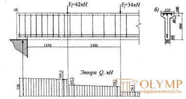
Черт.3.22. К примеру расчета 15
Payment. ho = 890 - 80 = 810 мм.
Определим требуемую интенсивность хомутов qsw согласно п.3.33,а, принимая длину проекции сечения с, равной расстоянию от опоры до первого груза – c 1 = 1350 мм. Тогда a 1 = c 1 / ho = 1350/810 = 1,667 < 2, и, следовательно, a 01 = a 1 = 1,667.
Определяем 
Согласно черт.3.22 поперечная сила на расстоянии с 1 от опоры равна Q 1 = 105,2 кН. Then  и, следовательно, qsw определяем по формуле (3.51):

Определим qsw при значении с , равном расстоянию от опоры до второго груза - с 2 = 2850 мм:
a2 = c2 / ho = 2850/810 = 3,52 > 3; принимаем a2 = 3,0.
Поскольку a2 > 2, принимаем a02 = 2,0.

Соответствующая поперечная сила равна Q 2 = 58,1 кН. Then

и, следовательно,

Принимаем максимальное значение qsw = qsw 1 = 60,7. Из условия сварки принимаем диаметр хомутов 8 мм ( Asw = 50,3 мм2). Тогда максимально допустимый шаг хомутов на приопорном участке равен

Принимаем sw 1 =100 мм. Назначаем шаг хомутов в пролете равным sw2 = 300 мм. Тогда интенсивность хомутов приопорного участка

а пролетного участка

Зададим длину участка с шагом хомутов sw 1, равной расстоянию от опоры до первого груза – l 1 = 1350 мм, и проверим условие (3.44) при значении с, равном расстоянию от опоры до второго груза - с = 2850 мм. Но поскольку 3 ho = 3·810 = 2430 мм < с, принимаем с = 2430мм. Значение Qsw определяем согласно п.3.34.
Так как 2 ho + l 1 = 2·810 + 1350 = 2970 мм > с , значение Qsw определяем по формуле (3.56). При этом, поскольку с > 2 ho , с о = 2 ho = 1620 мм.
Qsw = 0,75[ qsw 1 c o - ( qsw 1 - qsw 2)( c - l 1)] = 0,75[85,5·1620 - (85,5 -28,5)(2430 -1350)] =
57712 Н = 57,7 кН.
При с = 3 ho , Qb = Qb. min = 0,5 Rbtbhо = 0,53·0,75·80·810 = 24300 H = 24,3 кН.
Поперечная сила на расстоянии с = 2430 мм от опоры (черт.3.22) равна

Проверяем условие (3.44)
Qb + Qsw = 24,3 + 57,7 = 82,0 кН > Q = 59,5 кН,
those. прочность этого наклонного сечения обеспечена.
Большее значение с не рассматриваем, поскольку при этом поперечная сила резко уменьшается.
Таким образом, длину участка с шагом хомутов sw l = 100 мм принимаем равной 1,35 м.
Example 16 . Given : dvukhskatnaya beam span 8.8 m (Fig.3.23, a); continuous uniformly distributed load on the beam q = 46 kN / m; dimensions of the support section in fig. 23.23, b; concrete class B20 ( Rbt = 0.9 MPa); clamps made of reinforcement class А400 ( Rsw = 285 MPa) with a diameter of 10 mm ( Asw = 78.5 mm2) with a pitch sw = 100 mm.
It is required to check the strength of the inclined section by the transverse force.
Payment.The working height of the support section is ho = 600 - 40 = 560 mm (see drawing 3.3.23, b). According to the formula (3.48)


Figure 3.23. For example, calculating 16
We define the projection of the unfavorable oblique section with in accordance with clause 3.7. From drawing 3.3.23, and we have tg β = 1/12, b = 100 mm,
Rbt b = 0.9 · 100 = 90 N / mm; 1 - 2tg β = 1 - 2/12 = 0.833.
Since qsw / ( Rbtb) = 223.7 / 90 = 2.485> 2 (1 - 2tg β ) 2 = 2 · 0.8332 = 1.389, the value с is calculated by the formula (3.62).

The working height of the cross section ho at a distance c = 444 mm from the support is equal to
ho = ho 1 + s · tg β = 560 + 444/12 = 597 mm.
Since c = 444 mm <2 h o , c o = c = 444 mm;


Check the condition (3.44), taking the shear force at the end of the inclined section equal to
Q = Qmax - q 1 c = (46 · 8.8) / 2 - 46 · 0.444 = 182.0 kN:
Qb + Qsw = 108.4 + 74.5 = 182.9 kN> Q = 182 kN,
those. strength of oblique sections by transverse force
provided.
Example 17. Given : a console with dimensions according to Fig.3.24, a concentrated force on the console F = 130 kN, located at a distance l 1 = 0.8 m from the support; concrete class B15 ( Rbt = 0.75 MPa); Two-branch clamps with a diameter of 8 mm ( Asw = 101 mm2) from reinforcement class A240 ( Rsw = 170 MPa) with a pitch sw = 200 mm.
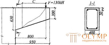
Chert.3.24. For example, the calculation of 17
It is required to check the strength of oblique sections by transverse force.
Payment. According to p.3.38, we check from the condition (3.44) the unfavorable inclined section starting from the point of application of the concentrated force, with the value of с defined by the formula (3.62) with q 1 = 0 and  .
.
The working height at the point of application of the concentrated force is equal to  (see Figure 3.24); Rbtb = 0.75 · 200 = 150N / mm.
The value of qsw is equal to


Insofar as  , we leave with = 469,4 mm.
Determine the working height h o at the end of the inclined section
h0 = h0 l + s · tg β = 305 + 469 · 0.369 = 478 mm.
Since c = 469.4> 2 ho, c o = c = 469 mm.

 ;
;
Qb + Qsw = 109.6 + 30.2 = 139.8 kN> F = 130 kN,
those. the strength of the inclined sections of the transverse force is provided.
Example 18 It is given : a continuous plate of the bottom of a tank without transverse reinforcement with a size of 3x6 m and thickness h = 160 mm, monolithically connected along the perimeter with beams; full uniformly distributed load 50 kN / m2; concrete class B15 ( Rbt = 0.75 MPa).
It is required to check the strength of the slab for the effect of transverse force.
Payment. ho = 160 - 20 = 140 mm. The calculation is carried out for a strip with a width of b = 1.0 m = 1000 mm, a span of l = 3 m. Then q = 50 · 1.0 = 50 kN / m, and the lateral force at the support is equal to

Check condition (3.64)
2.5 Rbtbh0 = 2.5 · 0.75 · 1000 · 140 = 262500 N> Qmax = 75 kN.
Check the condition (3.66), taking q 1 = q - 50 kN / m (N / mm). Since the lateral edges of the slab are monolithically connected to the beams, condition (3.66) has the form

therefore, the strength of the slab is checked from the condition (3.67a)
0.625 Rbtbhо + 2 hо q 1 = 0.625 · 0.75 · 1000 · 140 + 2.4 · 140 · 50 = 82425 N =
82.4 kN> Qmax = 75 kN,
those. the strength of the plate in transverse force is provided.
Example 19 Given : cantilever-type tank wall panel with a variable thickness from 262 (in termination) to 120 mm (at the free end) with a departure of 4.25 m; the lateral pressure of the soil, taking into account the load from vehicles on the soil surface, decreases linearly from q o = 55 kN / m2 in embedding to q = 6 kN / m2 at the free end; a = 22 mm; concrete class B15 ( Rbt = 0.75 MPa).
It is required to check the strength of the panel for the action of transverse force.
Payment. The working height of the cross section of the panel in the termination is ho1 = 262-22 = 240 mm.
We define tan β ( β is the angle between the stretched and compressed faces):
tg β = (262-120) / 4250 = 0.0334.
Check the conditions of paragraph 3..41. The shear force in the termination is
Qmax = ((55 + 6) / 2) · 4.25 = 129.6 kN.
The calculation is made for a panel strip with a width of b = 1.0 m = 1000 mm.
Check the condition (3.64), assuming ho = ho1 = 240 mm.
2.5 Rbtbho = 2.5 · 0.75 · 1000 · 240 = 450000 N = 450 kN> Qmax
those. condition is met.
Since the panels are connected to each other, and the width of the tank wall is obviously more than 5 h, the value of cmax is determined by the formula

The average intensity of the load on the support area with a length of cmax = 554 mm is equal to

Insofar as

take with = cmax = 554 mm.
Determine the working height of the section at a distance of C / 2 from the support (i.e., the average value of h o within the length of c )
 .
.
The shear force at a distance c = 554 mm from the support is equal to:
Q = Qmax - q 1 c = 129.6 - 51.8 · 0.554 = 100.9 kN.
Check the condition (3.65):

those. the strength of the panel in transverse force is provided.
Calculation of inclined sections for the effect of moment
Example 20. Given: a freely supported beam with a span of l = 5.5 m with a uniformly distributed load q = 29 kN / m; the design of the support section of the beam is adopted according to Fig.3.25; concrete class B15 ( Rb = 8.5 MPa); longitudinal reinforcement without anchors of class А400 ( Rs = 355 MPa) with sectional area As = 982 mm2 (2Æ25); clamps of A240 class reinforcement ( Rsw = 170 MPa) with a diameter of 8 mm and sw = 150 mm pitch are welded to the longitudinal rods.
It is required to check the strength of the inclined sections for the effect of the moment.
Payment. h o = h - a = 400 - 40 = 360 mm. Since stretched reinforcement does not have anchors, the calculation of inclined sections for the effect of the moment is necessary.
We determine the force in the tensioned reinforcement by the formula (3.73).
Take the beginning of an inclined section at the edge of the support. From here ls = ls up - 10 mm = 280 - 10 = 270 mm (see drawing 3.3.25).
The support reaction of the beam is equal to

and the beam bearing area As up = bls up = 200 · 280 = 56000 mm2,
from where 
 ,
,
therefore, a = 1.0. From table.3.3 with concrete class B15, class of reinforcement A400 and a = 1.0, we find λ an = 47. Then, the anchoring length is equal to lan = λ an ds = 47 · 25 = 1175 mm.
Ns = RsAs ( ls / lan ) = 355 · 982 · (270/1175) = 80106 N.
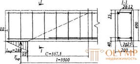
Damn.3.25. For example, calculating 20
Since 4 vertical and 2 horizontal transverse rods are welded to stretched rods within the length ls (see Fig.3.25), we will increase the forces Ns by the value Nw.
Taking dw = 8 mm, nw = 6 , φw = 150 (see table 3.4), we get
Nw = 0.7 nw φw dw2 Rbt = 0.7 · 6 · 1502 · 0.75 = 30.24 · 103 N.
From here, Ns = 80106 + 30240 = 110346 N.
Determine the maximum allowable value of Ns . From table.3.3 with a = 0.7 we find λ an = 33; then  i.e. leave Ns = 110346 N. Define the shoulder of the inner pair of forces

Then the moment perceived by the longitudinal reinforcement is
Ms = Nszs = 110346 · 327.5 = 36.1 · 106Nmm.
By the formula (3.48) we calculate the value of qsw

We determine the length of the projection of the most unfavorable inclined section by the formula (3.76), taking the value Qmax equal to the support reaction of the beam, i.e. Qmax = Fsup = 80 kN.

Then the moment perceived transverse reinforcement is equal to
Msw = 0.5 qswc 2 = 0.5 · 114.5 · 557.52 = 17.8 · 106 N mm.
The moment in the inclined section is defined as the moment in the normal section, located at the end of the inclined section, i.e. at a distance from the point of application of the support reaction, equal to x = lsup / 3 + c = 280/3 + 557.5 = 650.8 mm
 .
.
Check condition (3.69)
Ms + M sw = 36.1 + 17.8 = 53.9 kNm> M = 45.9 kNm,
those. the strength of the inclined sections at the bending moment is provided.
Example 21 It is given : a crossbar of a multistory frame with diagrams of moments and lateral forces from a uniformly distributed load q = 228 kN / m according to draft 3.26; concrete class B25; longitudinal and transverse reinforcement class A400 ( Rs = 355 MPa, Rsw = 285 MPa); cross-section of the priporny site - according to Fig.3.26; three-branch clamps with a diameter of 10 mm ( Rsw = 236 mm2) with a sw pitch equal to 150 mm.
It is required to determine the distance from the left support to the point where the first rod of the upper reinforcement breaks.
Payment. From drawing 3.26, we have: ho = h - a = 800 - 60 = 740 mm; a -50 mm; the cross-sectional area of the upper tensile reinforcement without taking into account one broken rod Æ32 As = 1609 mm2 (2Æ32); As = 2413 mm2 (3Æ32). We define the limiting moment corresponding to this reinforcement by the formula (3.19), since As < A ' s, i.e. x <0:
Mult = RsAs ( h o - a ' ) = 355 · 1609 · (740 - 50) = 394.1 · 106 N mm = 394.1 kNm.
On the plot of moments we determine the distance from the support to the point of theoretical breakage of the first rod from the equation

from where  where
where 

The shear force at the location of the theoretical cliff is
Q = Qmax - q · x = 620 - 228 · 0.355 = 539 kN.
Determine the value of qsw,

Insofar as  m, the length w, to which it is necessary to lead the breakable rod for a theoretical break point, is determined by the formula (3.79)
 .
.
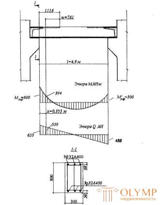
Chert.3.26 . For example, calculating 21
Consequently, the distance from the support to the point of breakage of the rod can be taken equal to x + w = 355 + 761 = 1116 mm.
Let us determine the required distance lan from the point where the rod breaks to the support section, assuming full use of this rod in the reference section. For this, according to the table.3.3, at a = 1.0 class of concrete B25, class of reinforcement A400, we find λ = 34. Then lan = λ an d = 34 · 32 = 1088 mm <1116 mm.
Therefore, we break the rod at a distance of 1116 mm from the support.
Что бы оставить комментарий войдите
Комментарии (0)