From the enterprises of the construction industry, the piles are delivered ready for submersion. Depending on the characteristics of the soil, there are a number of methods for piling, including impact, vibration, indentation, screwing, using undermining and electroosmosis, as well as various combinations of these methods.
The impact method is based on the use of impact energy (impact of a shock load), under the action of which the pile, with its lower pointed part, is embedded in the ground. As it dives, it shifts the soil particles to the sides, partially down or up. As a result of immersion, the pile displaces the volume of soil, almost equal to the volume of its submerged part. A smaller part of this soil turns out to be on the day surface, a large one — it mixes with the surrounding soil and considerably compresses the soil foundation. The zone of noticeable soil compaction around the pile is 2 ... 3 of the pile diameter.
Special mechanisms create a shock load on the pile top:
air / steam hammers driven by compressed air or steam, directly acting on the hammer of the hammer;
diesel hammers, whose work is based on the transfer of the energy of burning gases to the shock of the hammer;
vibratory pile drivers - transmission of oscillatory movements of the working member to a pile (use of vibration);
vibratory hammers - a combination of vibration and shock impact on the pile.
Vibratory pile drivers and vibratory hammers are more often used when sinking tubular piles of large diameter shells, when sinking into the ground and removing sheet piles.
The working cycle of hammers of all types consists of two cycles: idling, during which the striking part rises to a certain height, and the working stroke, during which the striking part moves downwards with great speed until the moment of impact on the pile. In a number of pile hammers, the working stroke occurs only under the action of the mass of the impact part, such hammers are called single action hammers.
In double action hammers at the point of maximum lift, the impact part receives additional energy; this energy and the weight of the impact part of the hammer act on the pile. In the process of working the hammer, its body remains motionless on the head of the submerged pile, the hammer's impact part moves inside the body. The energy of combustion not only raises the hammer's impact part to the utmost height, but also acts on it with a blow when it falls down under the action of gravity. The fuel supply and its ignition, depending on the position of the shock part, are carried out automatically.
Diesel hammers, as compared with air-steam engines, are distinguished by higher productivity, ease of operation, autonomy of action and lower cost. Autonomy is ensured by lifting due to the working stroke of a two-stroke diesel engine.
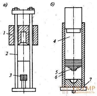
On building sites, sucker-rod and tubular diesel hammers are used (Fig. 4.5). Shock part of diesel engine hammers - movable cylinder, open at the bottom and moving in guide rods.
When the cylinder falls on a fixed piston in the combustion chamber, a mixture of air and fuel is ignited. The gases resulting from the combustion of the mixture throw the cylinder upwards, after which a new blow occurs and the cycle repeats.
In tubular diesel hammers, a stationary cylinder with a heel is the guide of the entire structure. Shock part - the mobile piston with a head. The ignition of the mixture occurs when the piston head strikes the surface of the spherical cavity of the cylinder.
The main advantage of a diesel hammer of a tubular type over a sucker rod is that, with the same mass of the impact part, they have a significantly higher (2 ... 3 times) impact energy.
We recommend the following ratio of the mass of the impact part of the hammer to the pile weight: for sucker-type hammers 1.25; for tubular - 0.5 ... 0.7. For single action hammers, the number of 1 minute strikes is 45 ... 100, the mass of the striking part is up to 2500 kg. Similarly, for double action hammers, the number of strokes per minute is up to 300, the mass of the striking part is up to 1200 kg.
A hammerhead is included in the hammer kit , which is necessary to secure the pile in the guides of the pile-driving installation, protect the pile head from destruction by hammer blows and evenly distribute the blow over the pile area. In this regard, the internal cavity of the head cover should correspond to the outline and size of the pile head and be rigidly fixed on it.
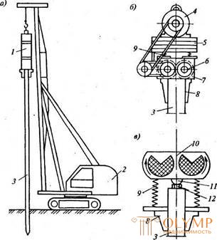
For lifting and installing the pile in a predetermined position and for driving piles to ensure the transfer of force from the hammer of the pile strictly in the vertical position, use special devices - riders (Fig.4.6). The main working part of the copra is its arrow, along which the hammer is installed before the dive, the hammer is lowered and raised as the pile is driven. Inclined piles are immersed in soil with an inclined boom. Copra are on the rail (universal metal tower-type copra) and self-propelled - based on cranes, tractors, excavators and cars with a boom length of 9 ... 18 m.
Fig. 4.5. Diesel hammers schemes: and - shtangovy; b - tubular; 1 - movable cylinder; 2 - guide rods; 3-piston; 4 - movable piston; 5 - head; b - fixed cylinder; 7 - supporting part | Universal pile drivers have a significant intrinsic weight of up to 20 tons. Installation and disassembly of such pile drivers, installation of crane runways for them is quite labor-intensive processes, therefore universal pile drivers are used for driving piles longer than 12 m with a large amount of pile work on the site. The most common in industrial and civil construction are piles with a length of 6 ... 10 m, which are driven by self-propelled piling units. Such units are maneuverable and have mechanical devices for lifting and raising the pile to the required height, fixing the pile head in the cap, in the vertical alignment of the boom with the pile before driving. |
Pile driving consists of three main repetitive operations:
■ shifting and installing copra in place of pile driving;
■ raising and installation of a pile in a position for driving;
■ pile driving.
The center of gravity of the pile hammer should coincide with the direction of pile driving. Pile hammer raise to a height sufficient to install the pile, with some margin on the course of the hammer and secure in this position. When driving steel and reinforced concrete piles with single action hammers, it is necessary to use head covers to cushion the blow and to protect the pile head from destruction.
The process of pile driving includes installation of a pile in the design position, putting on the cap, lowering the hammer and the first strikes on the pile from a height of 0.2 ... 0.4 m, after the pile is immersed to a depth of 1 m, the transition to the normal driving mode. From each stroke, the pile sinks to a certain depth, which decreases as the pile deepens. In the future, there comes a time when the depth of the pile driving is almost imperceptible. Virtually pile sinks into the ground at the same small value, called failure.
Failure - immersion depth - piles for a certain number of blows, usually a single action hammer or per unit time for double action hammers. The failure rate is the average of 10 or a series of shots per unit of time.
Pledge - a series of blows performed for measuring the average failure rate: for air-steam hammers in a pledge of 20 ... 30 blows; for diesel hammers in the pledge 10 hits; for diesel hammers double action failure is determined for 1 min. driving.
Measurements are carried out with an accuracy of 1 mm, the stop is stopped when a specified failure is calculated (calculated).
If the average failure in three consecutive deposits does not exceed the calculated one, then the pile driving process is considered complete.
If during the diving the pile did not reach the design mark, but the specified failure was already received, then this failure may be false, due to the possible overvoltage in the ground from the previous pile driving.
Fig. 4.6. Pile driving machines: a - pavement; b - universal rail; in - on the basis of the excavator; Mr. tractor; d - by car; 1 - cab; 2 - bridge mast; 3 - bridge; 4 - rail track; 5 - pile; 6 - ogolovnik with blocks; 7 - trolley; 8 - turntable; 9 - hammer; 10 - base machine; 11-shot; 12 - strut; 13 - hydraulic cylinder; 14-retractable mechanism; 15 - hydraulic cylinder lift and tilt boom; 16 - pile lifting mechanism; 17 - movable frame | After 3 ... 4 days the pile can be plunged to the design mark. Pile vibrations are carried out using vibratory mechanisms that turn dynamic loads on the pile. The immersion speed and the amplitude of oscillations are influenced by the mass of the vibrating parts of the pile and the vibrator, its eccentricity, the density of the soil participating in the oscillations, the frequency of oscillation of the vibrator. Thanks to the vibrating radio for immersing piles in the ground |


sometimes efforts are required ten times smaller than when driven. When this occurs, the soil is partially compacted, including under the pile head. The compaction zone for different soils is 1.5 ... 3 pile diameters. To immerse piles in the ground by vibrating, vibratory pile drivers are used , which are suspended from the mast of a pile immersion installation and rigidly connected to the pile cap. The action of the vibrator is based on the principle that imbalances
vibrator horizontal centrifugal forces are mutually eliminated, while the vertical forces are added together. The amplitude of the vibration oscillations and the mass of the vibration system, which includes the pile, the caps and the vibrator, must ensure the vibration of adjacent layers of soil, their inclusion in this system, resulting in the separation of the soil grains under the contour of the submerged part of the pile.
The method is most acceptable in sandy soils, water-saturated fine and silty soils, where the sink rate can reach 3.5 ... 7 m / min. With this method, solid and hollow reinforced concrete piles, shell piles, and metal sheet piling are immersed.
Fig. 4.7. Pile vibration: a - svapogruzhayuschaya installation; b —vibropogruzhatel with sprung loading; v- vibrohammer; 1- vibrator; 2 - excavator; 3 - pile; 4- electric motor; 5 - loading plates; b - vibrator; 7 - unbalances; 8 - headgear; 9 - springs; 10 - shock with an electric motor; 11 - peen; 12 - the anvil | When clay and heavy loamy soils under the tip of the pile may be clay pad, which reduces the bearing capacity of the pile up to 40%. Therefore, in the final stage of immersion, in the last 15 ... 30 cm, the pile is immersed in the ground by the impact method. When choosing low-frequency immersions (up to 420 count / min) used for immersion of heavy reinforced concrete piles and tubular piles with a diameter of 1000 mm or more, it is necessary that the eccentric moment exceeds the mass of the vibrating system at least 7 times for light soils and 11 times for medium and heavy soils. For immersion of light piles weighing up to 3 tons and a metal tongue in soils that do not have a large frontal resistance under the tip of the pile, apply high-frequency (from 1500 count / min) vibropogruzhateley with spring-loaded preload, consisting of |
vibrator and attached to it by means of a spring system additional load with an electric motor located on it.
The vibration method is most effective in non-coherent water-saturated soils. The application of the method for the immersion of piles into low-moisture dense soils is possible only with the construction of leading wells, i.e., with preliminary drilling of wells.
A more versatile is the vibro-impact method of piling using vibratory hammers. During the work of the vibro-hammer, along with the vibration effect on the pile, the drummer periodically lowers, exerting a dynamic effect on the pile head.
The most common spring vibratory hammers. In them, as the shafts are rotated with unbalances in opposite directions, constant oscillations are created. When the gap between the drummer and the anvil of the pile is less than the amplitude of oscillations, the striker periodically strikes the pile through the anvil. Vibrating hammers can self-adjust, i.e., increase the impact energy with an increase in the resistance of the soil to the immersion of the pile. The mass of the shock part of the vibratory hammer in relation to the plunging of reinforced concrete piles must be at least 50% of the mass of the pile and be 650..1350 kp.
Vibro-shock method is applicable in connected dense soils, and allows 3 ... 8 times faster with the same power as the vibrating method to carry out the immersion of piles into the soil due to simultaneous vibration and driving. In this case, a rigid connection between the vibrator and the pile must be ensured.
The vibro-indentation method is based on a combination of vibratory or vibro-impact effects on a pile and static weights. Vibration setting consists of two frames. On the rear frame there is an electric generator powered by a tractor engine and a two-drum winch, on the front frame there is a guide boom with a vibratory pile driver and blocks through which the pressing cable from the winch passes to the vibratory pile driver. In the working position, the vibrator, located above the place of immersion of the pile, lifts the pile and sets it together with the fixed head-board in place of its driving. When the vibratory pile driver and winch are turned on, the pile is immersed due to its own weight, the weight of the vibratory pile driver and part of the tractor weight transmitted by the pressing cable through the vibratory pile driver to the pile. At the same time, vibration is generated on the pile by a low-frequency submersible with a sprung plate.
The method of vibroinavigate does not require the device paths for shifting the working unit, eliminates damage and destruction of the piles. Especially effective when piling up to 6 m in length.
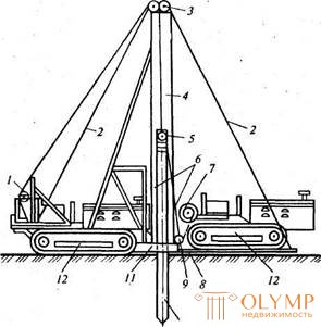
Dive piles indentation is used for short piles of solid and tubular section (3 ... 5 m). Static indentation is carried out in such a sequence: the pile is installed in a vertical position in the guide boom of the unit. Next, the head is lowered and fixed to the pile head, transmitting pressure from the base machine (tractor, excavator) through the system of blocks and tackles directly onto the pile, which, thanks to this pressure, is gradually sank into the ground. After the pile reaches the design mark, the immersion is stopped, the cap is removed, the unit is moved to a new position. Static indentation is applicable using two mechanisms simultaneously activated (Fig. 4.8).
Fig. 4.8. The scheme of immersion pile static pressure: 1 - winch and traction rope for lowering the base plate and lifting the cap; 2 - boom extensions; 3 - blocks; 4 - boom frame; 5 - headgear with blocks; 6 - push-in rope; 7 -injection winch; 8 - base plate; 9 - tap-off unit; 10 - pile; 11 - frame; 12 - tractor | Погружение свай завинчиванием основано на завинчивании стальных и железобетонных свай со стальным наконечником с помощью мобильных установок, смонтированных на базе автомобилей или других самоходных средств. Метод применяют чаще всего при устройстве фундаментов под мачты линий электропередачи, радиосвязи и других сооружений, где в достаточной мере могут быть использованы несущая способность винтовых свай и их сопротивление выдергиванию (рис. 4.9). Установка для завинчивания состоит из рабочего органа, приводов вращения и наклона рабочего органа, гидросистемы, пульта управления, четырех гидравли-ческих выносных опор и вспомога-тельного оборудования. Рабочий орган кабестан - механизм, состоящий из двух пар захватов и электродвигателя. Захваты обжимают сваю и передают ей вращение от электродвигателя. В зависимости от назначения (передачи нагрузки на большую площадь или |
заглубления в плотные грунты) винтовые лопасти наконечников могут иметь в диаметре до 3 м, минимальный диаметр лопастей составляет 30 см; длина свай может превышать 20 м. Конструкция рабочего органа позволяет выполнять следующие операции: втягивать винтовую сваю внутрь трубы рабочего органа (предварительно на сваю надевают инвентарную металлическую оболочку), обеспечивать заданный угол погружения сваи в пределах 0...45о от вертикали, погружать сваю в грунт путем вращения с одновременным использованием осевого усилия. Это усилие при необходимости можно использовать при вывертывании сваи из грунта. Вращение рабочего органа осуществляют от коробки отбора мощности через соответствующие редукторы.
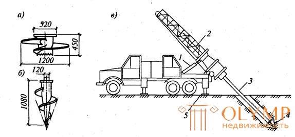
Fig. 4.9. Схема процесса завинчивания свай:
1 - конструкция наконечника при погружении в слабые грунты; б — то же, в плотные грунты; в схема погружения сваи; 1 - редуктор наклона рабочего органа; 2 - рабочий орган (кабестан); 3 -свая; 4 - наконечник сваи; 5 - выносные опоры
Рабочие операции при погружении сваи методом завинчивания аналогичны операциям, выполняемым при погружении свай методами забивки или вибропогружения. Только вместо установки и снятия наголовника при этом методе одевают и снимают металлическую оболочку.
После завинчивания винтовой сваи (диаметр труб достигает 1 м), ее внутренняя полость заполняется бетоном. Скорость погружения винтовых свай зависит от диаметра лопасти и характеристик грунта и находится в пределах 0,2...0,6 м/мин.
Достоинства винтовых свай в их высокой несущей способности, возможности плавного погружения в грунт, восприятии отрицательных усилий.
Погружение свай подмывом грунта применяют в несвязных и малосвязных грунтах - песчаных и супесчаных. Целесообразно подмыв использовать для свай большого поперечного сечения и большой длины, но недопустимо для висячих свай. Способ заключается в том, что под действием воды, вытекающей под напором у острия сваи из одной или нескольких труб, закрепленных на свае, грунт разрыхляется и частично вымывается (рис. 4.10). При этом сопротивление грунта у острия сваи снижается, а поднимающаяся вдоль сваи вода размывает прилегающий грунт, уменьшая тем самым трение по боковым поверхностям сваи. В результате свая погружается в грунт под действием собственной массы и массы установленного на ней молота.
Расположение трубок для подмыва грунта диаметром 38...62 мм может быть боковым, когда две или четыре трубки с наконечниками находятся по бокам сваи, и центральным, когда одно- или многоструйный наконечник размещен в центре пустотелой забиваемой сваи. При боковом подмыве, по сравнению с центральным подмывом, создаются более благоприятные условия для уменьшения сил трения по боковой поверхности свай. При боковом расположении подмывные трубки крепят таким образом, чтобы наконечники находились у свай на 30...40 см выше острия.
The water is less than 0.5 MPa. There is a tendency for the pile to go down. If you’re taking a load of water, you’ll take it pile driver 40% compared to a clean padding, fuel is saved. The soil level is compacted tightly.
 The use of the method of undermining is not allowed if there is a threat of subsidence of nearby structures, as well as in general on subsiding soils.
|
|
Fig. 4.10. Undermining of soil for immersion of piles: and - immersion of square piles with an underwash of soil; 1 - hammer; 2 - a cable that supports flushing tubes; 3 - pressure hose; 4 - flushing pipes; 5 - pile; 6-location of the flushing lines; in - the tip of the wash water | |
Dipping piles using electro-osmosis is used in water-saturated, dense clay soils, in moraine loams and clays. For the practical implementation of the method, the pile already immersed in the ground is connected to the positive pole (anode) of the DC power grid, and the neighboring one, prepared for immersion in the ground, is connected to the negative pole (cathode). When current is turned on around a pile with a positive pole, the soil moisture decreases sharply, while on the other side with a negative pole it sharply increases. In a more humid environment, the pile quickly sinks into the ground, which allows the use of piling equipment of lesser capacity.
After the completion of driving and detaching the piles from the current source in the soil, the former stabilization of the soil and its moisture state is quickly restored. Due to this, only due to a decrease in humidity around a driven pile, its carrying capacity increases significantly.
If the reinforced concrete piles with the osmosis method are additionally equipped with metal strips, which will occupy 20 ... 25% of the side surface of the piles, and also connect the already driven pile to the anode, and immersed with metal strips to the cathode, only this will allow for 20 .. .30% reduction in labor costs and duration of immersion compared with the pure electroosmosis method. Compared with pile driving, the use of additional features of electroosmosis allows a 25 ... 40% acceleration of the process of piling into the ground.
The sequence of diving piles. The order of piling depends on their location in the pile field and the parameters of the pile loading equipment.
The sequence of pile driving is determined by the technical plan or the project of work, it depends on the size of the pile field and the properties of the soil.
Three schemes are applicable - ordinary, when all piles are sequentially driven in the same row; spiral, when driving piles from the center to the piles of external rows and sectional, when the whole field is divided into separate sections along the width of the building, in which driving is carried out according to the row scheme (Fig. 4.11). The spiral scheme provides for immersion of piles in concentric circles from the center to the edges of the pile fields that allows
Fig. 4.11. Scheme of an ordinary pile driving system: and - at a rectilinear arrangement of piles in separate rows; b- at the location of piles of bushes; 1 ... 15 - pile driving sequence | get the minimum length of the path of the submersible installation. In addition, when sinking piles around it, the ground is additionally compacted. In the spiral scheme, the newly driven piles are always located along the external contour of the pile field, therefore the intensity of the already driven field has a minimal effect. At large distances between individual piles, the sequence of immersion may be determined mainly by technological considerations, |
primarily used equipment. For some tower-type towers, masts rest on sliding frames displacing by about 1 m. You can hammer piles of two rows from one site at once with such copra, which significantly reduces the route of the copra and time for moving it. In the construction of the underground part of residential buildings, cranes equipped with mounted scraper equipment, moving along the rail track along the edge of the building pit, were used.
When constructing pile foundations of large buildings, it is rational to use a bridge pile-driving installation (Fig.4.12), which is a movable bridge along which the trolley with a pile driver moves.
Piles 8 ... 12 m long are hammered with a diesel hammer. The advantage of the bridge piling installation is the ability to accurately install the piles at the place of driving, the preliminary layout of the piles in the work area significantly reduces the operation
Fig. 4.12. Driving piling bridge piling installation: 1 - head with blocks; 2 - diesel hammer; 3 - pile; 4 — Piper; 5 - rails; 6 - mobile bridge; 7 - crane for piling | dragging and securing the pile on a scraper, which greatly improves the productivity and quality of work. When piling, the main factors determining the choice of method and piling equipment are the physical and mechanical properties of the soil, the volume of piling, the type of piles, the depth of their immersion, the performance of the pile driving installations and pile driving machines used. The volume of upcoming work is measured by the number of piles that need to be driven, or the total length of the part of piles that is immersed in the ground. From these volumes, the specifics of the soil conditions and the specified timing of work depends on the choice |
equipment for piling and the number of submersible installations
List of used sources
1.SNiP 2.02.03-85 (1995) Pile foundations.
2.SNiP 2.02.01-83 (1995) Foundations of buildings and structures.


 but)
but) 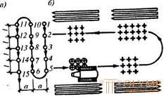


Что бы оставить комментарий войдите
Комментарии (0)