Constructive solutions for industrial building systems
Panel construction of residential buildings for experimental construction began to apply (in the USSR) from 1945, and for mass - from 1958. Episodic use of panel structures in the construction of public buildings dates back to the mid-60s, but only from the beginning of the 80s did their mass introduction begin.
The basis for the unification of the geometric parameters of structural products is a modular grid with a single enlarged module 6m (6000mm)
Adopted preferred flight range:
- along the building - 2.4 m; 3.0 m; 3.6 m; and 6.0 m; - across 6.0m; 5.4m; 4.8m;
Introduced a single binding of the coordination axes of the outer walls 100mm from the inner walls to the joint of the outer walls - 30mm, which allows to unify the assembling joints of the panels.
Structures of buildings monolithic and prefabricated monolithic building systems
Obvious is the close relationship of space-planning decisions, the chosen technology of construction and construction of buildings in monolithic housing construction.
There are several options for building systems, but they can be divided into two groups: walls are completely monolithic, containing a monolithic concrete layer (or belt), and walls that do not contain monolithic concrete inclusions.
Monolithic exterior walls are designed with single-layer lightweight concrete (density 1200-1450 kg / m3). The thickness of the walls in accordance with thermal requirements is accepted from 300 to 500 mm.
Precast - monolithic walls usually include a monolithic layer 120 mm thick made of heavy or constructive lightweight concrete. The prefabricated wall element - the shell - bears insulating and protective-finishing functions and is located outside the monolithic layer as a formwork to be left.
The shell can be - as a light-weight single-layer panel (density up to 900 kg / m3) with an external protective and finishing layer, or a panel of iso-constructive lightweight concrete with a density up to 1800 kg / m3 with heat-insulating liners, or a 80mm thick reinforced concrete shell with contour ribs and plate insulation or casting foam. The shell structures are attached to the monolithic layer on flexible steel bonds.
Prefabricated exterior walls are predominantly made of lightweight hinged panels. Along with them, it is possible to use hinged panels made of non-concrete materials as interwindow inserts.
Ceilings in the houses of a unified constructive-technological system are designed to be monolithic, prefabricated monolithic or prefabricated.
Monolithic reinforced buildings
Design and construction of civil buildings of monolithic reinforced concrete is one of the new and economical areas of industrial housing.
Architectural and planning possibilities of houses from monolithic reinforced concrete are very diverse. The use of buildings of this system allows the architect to solve problems that cannot be solved from standard prefabricated products (block, panel, etc.).
These buildings have greater strength and rigidity compared to panel ones, since they lack joints.
Houses of monolithic reinforced concrete can be built in areas that do not have an industrial base.
The transfer of technological processes to the construction site has the following disadvantages: the dependence of construction on climatic conditions; the need to perform finishing and sanitary works on the site; the inability to obtain high quality finishing work.
In the construction of buildings of monolithic reinforced concrete using different types of formwork.
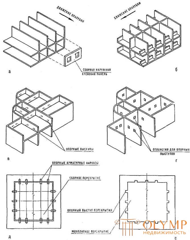
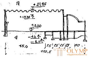
When the volume-adjustable formwork monolithic perform walls and floors, and the formwork after hardening the concrete move in the direction of the longitudinal or transverse walls (Fig. 150).
Another type of formwork with upward movement - sliding shield. In this case, the most effective technological process in which the vertical elements of the building are initially carried out - external and internal walls. During construction in the walls leave holes for sections of floor slabs. In this case, floors, slabs of balconies and loggias can be performed: monolithic, then install shield formwork with rebar in the supporting grooves; prefabricated, then the plates perform a special form and lead into the support holes.
In monolithic reinforced concrete houses, single, double, and three-layer exterior wall panels are used.
Overlaps can be monolithic, prefabricated and combined. Monolithic floors are the most rational, since the technology of their manufacture is continuous.
Elements of buildings from monolithic reinforced concrete are constantly (from the moment of manufacturing) in the working position, i.e. do not experience transportation, installation and other side loads. This reduces steel consumption compared to steel consumption in prefabricated buildings.
The complexity of the construction of buildings made of monolithic reinforced concrete is 40-50% higher than the complexity of the construction of large-panel buildings.
Monolithic overlappings are made with a thickness of 160 mm in the form of continuous multi-section plates of continuous section supported on supporting walls along a contour, or on three sides.
Precast monolithic overlappings consist in height of the spirit of the elements: the lower reinforced concrete slab 4–6 cm thick, performing the functions of permanent formwork and the upper monolithic layer 10–12 cm thick.
For prefabricated floors, typical panels of continuous section or hollow core slabs with a special modification of the ends are used. It consists in increasing the bevels of the ends, increasing the opening of the flooring voids and arranging reinforcement outlets for loop or welded connections between the element.
Long-span coatings
Architectural and constructive solutions of long-span designs differ a considerable variety. They are divided into planar and spatial .
To planar structures include those in which each carrier element, spanning the span, works only in its vertical plane.
Spatial large-span structures transmit to the supporting elements of the load, the direction and magnitude of which is determined by the statistical scheme of the work of this coating, its dimensions, its own mass, temporary loads.
Flat coatings
Beams and trusses - will be reviewed in the course "Architectural constructions of industrial buildings"
Frames and arches - the same.
Spatial constructions
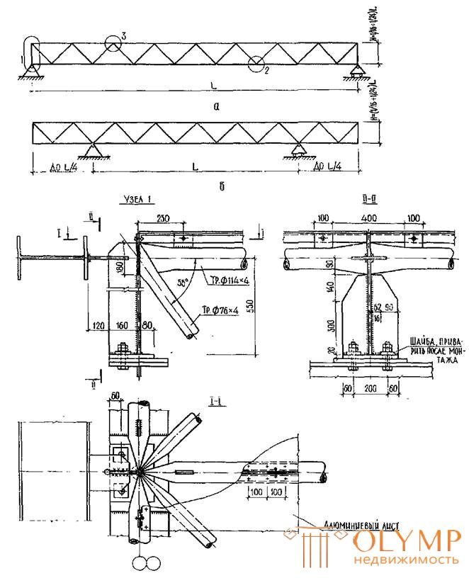
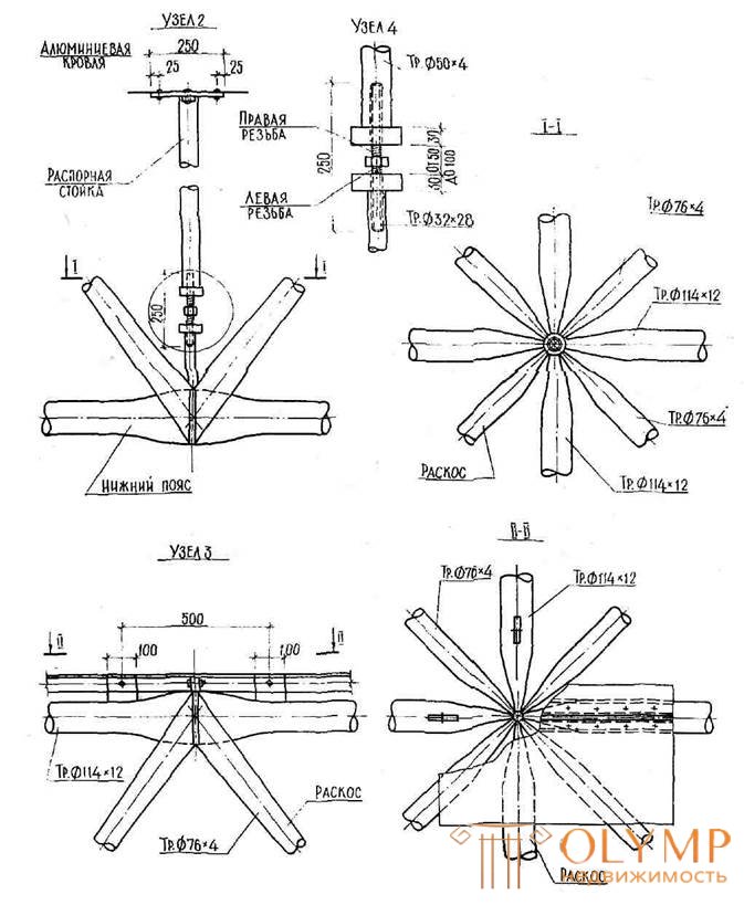
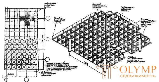
Structures are a cross system of beams or trusses with parallel belts. Structures perform trellised of pipes or corners. They intersect in horizontal, inclined planes and can be metal, reinforced concrete and wood.
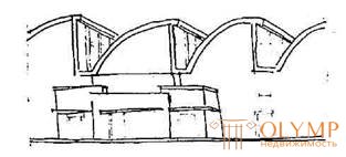
Due to the special architectural expressiveness of the interiors, economic use of the height of the room, the rare location of the supports, these structures are widely used in the coatings of civilian buildings (Fig. 151, 152, 153, 154.164, 165, 166, 167).
Hanging designs
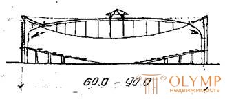
Hanging designs are the most effective designs of large-span structures of large-span coatings. Hanging is called all types of coatings, in which the main supporting structure, spanning the span, works in tension. An important advantage of these structures is the possibility of overlapping the span without intermediate supports.
Hanging structures are becoming more widely used in large-span public buildings: indoor stadiums, swimming pools, exhibition halls, indoor markets, train stations, concert halls, agricultural buildings, large-capacity warehouses, etc.
Cable covers
Cable-covered coatings are called coatings — the span of which is formed by a network of supporting flexible filaments (cables) with subsequent laying of enclosing elements onto it without ensuring their joint operation with each other and with the support contour.
Possessing a relatively small boom lifting or sagging (1 / 20-1 / 25 span), these coatings provide the smallest building height of the building, reduce internal volume and reduce the cost of the heating system and building operation.
The hanging cable structure can be erected over buildings of any shape in the plan , while on the same plane it is possible to arrange coatings having different surface shapes. Possessing large forms of shaping, the guy coats predetermine the architectural expressiveness of the building.
Membranes
The membrane is a thin flexible solid plate, which has a very high tensile strength, but negligibly small, almost bending Flexural rigidity. Therefore, the main stress state of the membrane is stretching.
Its thickness is usually prescribed not on the basis of strength, but for constructive reasons. The membrane can cover spans of 100-120m with a thickness of aluminum sheets not exceeding 1.5 mm.
Membranes are formed from steel or aluminum continuous sheets or tapes, artificial films or special fabrics that perform the functions of the main structural bearing, and the fencing (roofing) structure (Fig. 158, 159,160).
Spatial thin-sheet aluminum structures (in the form of membranes, prestressed shells, folds, tent surfaces, systems formed by interlacing aluminum tapes, etc.) have a negligible mass, are quite simple to manufacture and assemble, and therefore are increasingly used in coatings of large-span structures.
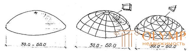
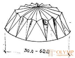
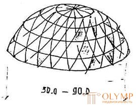
Domes
A dome is a spatial construction of a convex roof of a building or structure of a round, elliptical or polygonal shape in plan.
Domes are the most economical form of covering civil and industrial buildings.
Unlike vaulted roofs, domes have a non-linear, but a centric composition of a volume-spatial structure. The domes work mainly in compression with the transfer to the supports not only of vertical load, but also thrust.
With the advent of reinforced concrete, the widespread use of dome structures was resumed.
Recently, metal constructions of dome coatings have become widespread.
According to the design of the dome can be: smooth (shell), ribbed, sailing and wavy - made of reinforced concrete; ribbed and mesh - made of metal.
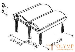
Vaults
Shells of the double curvature - they are used to cover the rectangular in terms of space. They rest on four sides on the diaphragm (trusses, arches, walls). The design features also include spherical sailing shells.
Barrel vaults - have a longitudinal axis, curved along a curve with a convexity upwards, most often circumscribed around the circumference.
Fig.150
Fig.151.
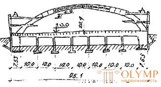
Fig.152.
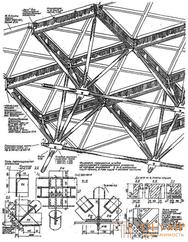
SPATIAL ROD SYSTEM OF TYPE OF STRUCTURE FROM STEEL TUBULAR PYRAMIDAL ELEMENTS ON THE EXAMPLE OF CLOSING 60x60m
FRACTURING FRAGMENT (bottom view)
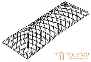
Fig.153.
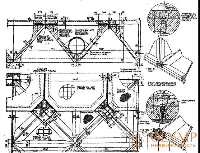
COATING IN THE FORM OF A REGULAR STRUCTURAL PLATE OF ARMOCEMENT ELEMENTS (IN SERIES 1.260 - 1)
Ribbed PLATE PLAN
AND PYRAMIDAL ELEMENTS
ASSEMBLY ELEMENTS AND KNOTS
JOINT OF PYRAMIDAL ELEMENTS IN THE FLIGHT
SUPPORT PYRAMIDAL ELEMENT
Fig.154.
Fig.155.
Fig.156.
COATING ARROW - VANTY FERMES OF THE FLIGHT WITH A GRID
V-SHAPED COLUMNS 12x72m.
CROSS SECTION
ACONOMETRIC SECTION
Longitudinal section of the block according to the building’s axle
Fig.157.
Fig.158.
Fig.159.
COATING OF THE STEEL SUSPENDING MEMBRANE IN THE VIDEO OF THE BALL SEGMENT BY RADIUS 404M WITH THE BASIS OF RADIUS 80M
Fig.160
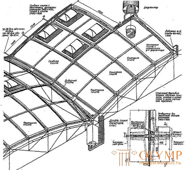
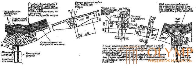
REINFORCED CONCRETE MULTI-WAVE SHELLS 18x24 AND 18x30m FROM 3x6M PLATES AND STEEL CONTOUR FARM
(SERIES 1.466 - 1)
1-1
SECTION IN THE DIRECTION
24 - METRO SPAN
2-2
SECTION IN THE DIRECTION
18 - METRO SPAN
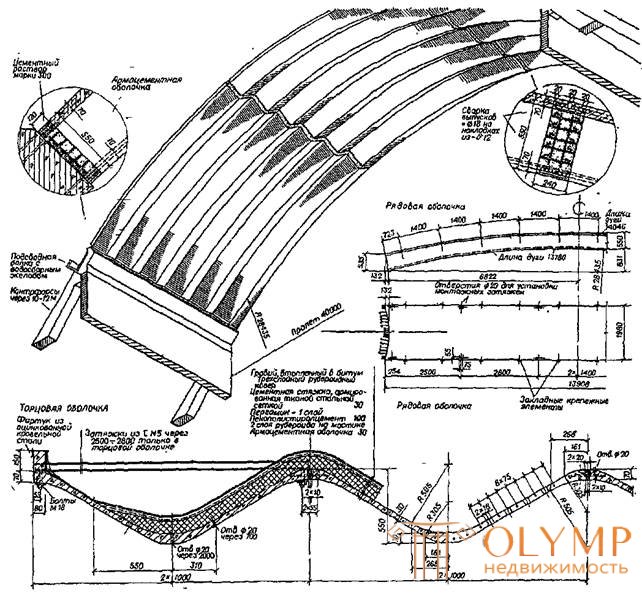
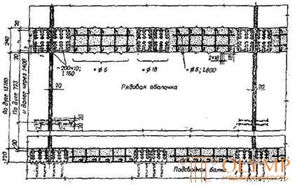
Fig.161.
CONSOLIDATED COATINGS FROM ARMOCEMENT ENVIRONMENTS SPACE 40m
MOUNTING SHEETS
1-1
2-2
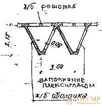
Fig.162.
Fig.163.
CROSS PILES
LEATHER SHELL
CROSS ARCH
REINFORCED CONCRETE DOME
Smooth
Ribbed - ring
Crystalline
METAL DOME FRAMES
Stellate
Mesh type "Zeiss"
Fig.164.
LENGTHWISE CUT
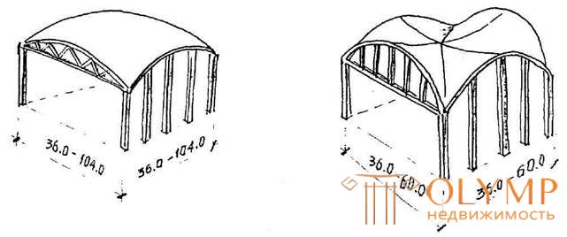
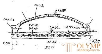
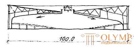
CYLINDRICAL ARCHES
CODE OF MAIN PAVILION OF EXHIBITION CENTER IN TURIN
1-1
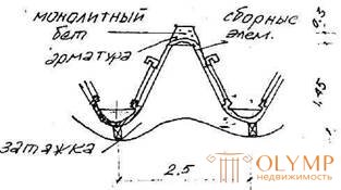
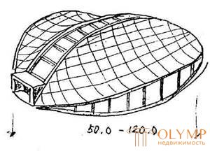
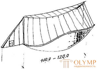
WAVE ARCHES
CROSS SECTION
COVER CODE OF THE PALACE OF INTERNATIONAL EXHIBITIONS IN NICE (FRANCE)
ARCH DETAIL
Fig.165.
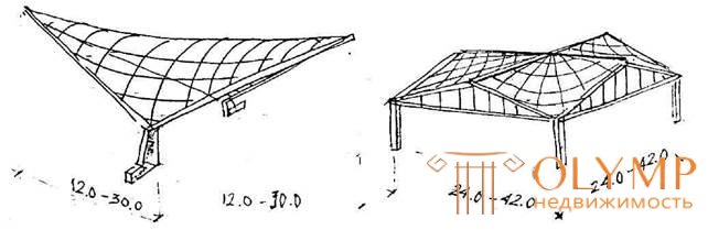
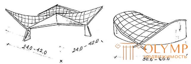
HYPERBOLIC PARABOLOIDS (HYPARS)
Single
The combination of single giparov
The combination of single giparov
Saddle coating
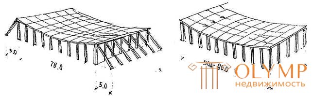
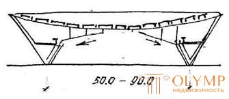
HANGING COATINGS ON A RECTANGULAR PLAN
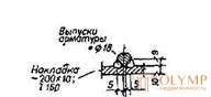
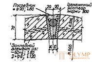
Coating with w / w straps
(garage in Krasnoyarsk)
Coverage without delays with shear segment
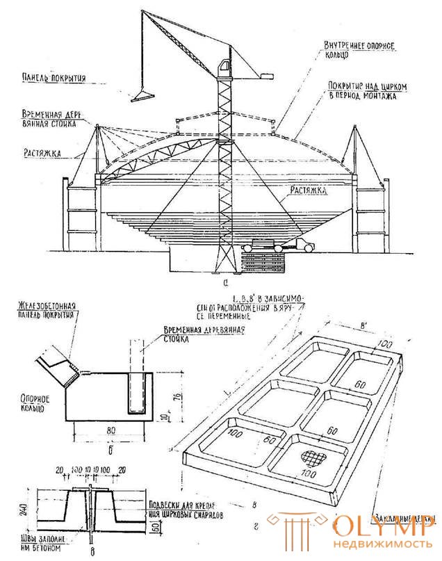
Fig.166.
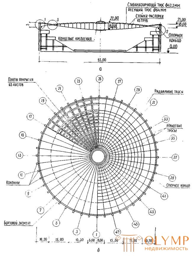
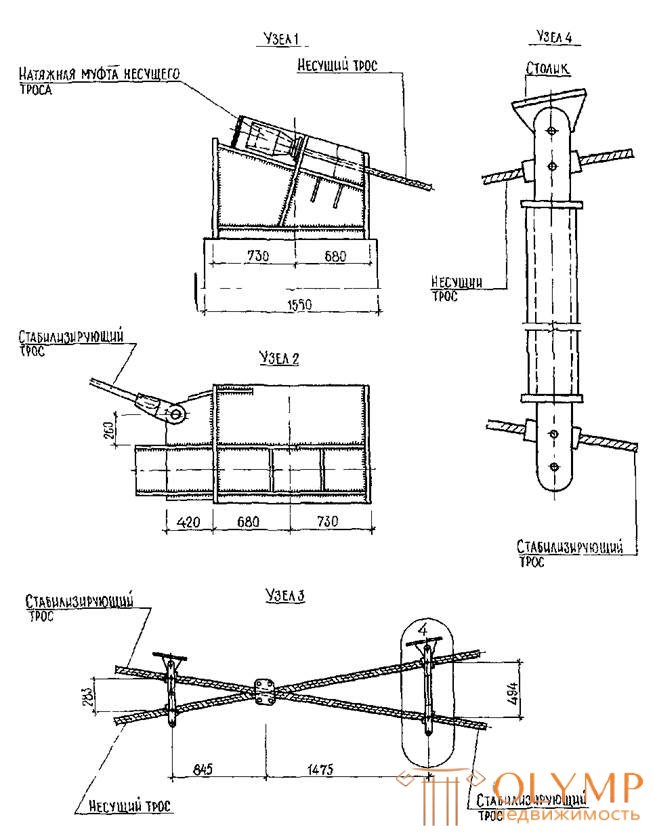
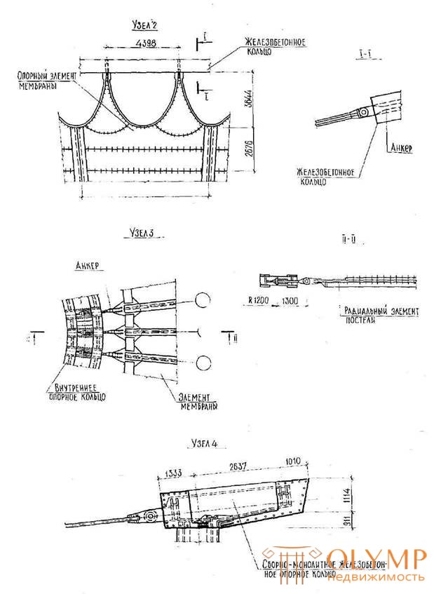
HANGING COATINGS ON ROUND PLAN
CUP COATING
(Baumansky market in Moscow)
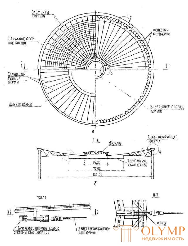
COATING TYPE "BIKE WHEEL"
(Palace of Sports "Jubilee"
in Leningrad)
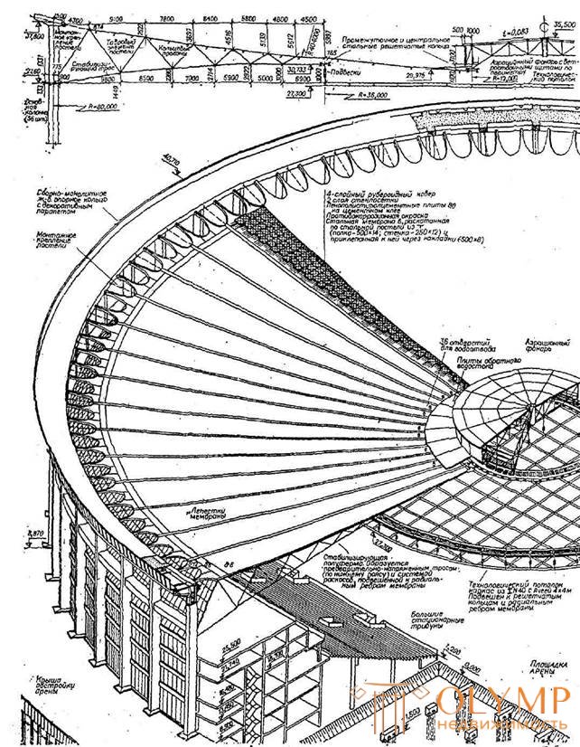
SHEET COATING OF THE UNIVERSAL SPORTS HALL IN THE REF. VICTORY IN LENINGRAD
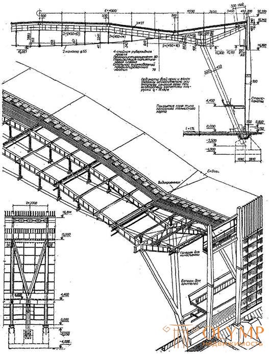
TWO-SCALE POSTER COATINGS
OLYMPIC BIKE COATING IN MOSCOW
SCHEME OF THE CONSTRUCTION OF THE SPORTS HALL IN TOKYO


Что бы оставить комментарий войдите
Комментарии (0)