The overlap is a horizontal internal protective structure that divides the height of adjacent rooms in a building or structure. As a rule, it is a supporting structure.
Overlaps
General information.
Requirements for overlapping. Classification.
Overlappings are at the same time bearing and protecting elements of buildings. They perceive permanent and temporary loads from their own weight, partitions, equipment, furniture, people and transfer them to vertical supports. The overlaps, together with those, are horizontal diaphragms connecting the vertical supporting structures among themselves and ensuring the stability of the building as a whole.
In addition, floors are also subject to impacts associated with the operation of the building (operating moisture, sound and airborne sound, etc.)
Overlaps along with the walls are the main structural parts of the building and largely determine the level of its efficiency.
The share of the cost of floors and floors is about 20-25% of the total value of the building, the complexity of the device flooring up to 20% of the total labor input of the building.
The following basic requirements are imposed on floors :
1. Strength, i.e., the ability to safely withstand all the loads acting on them;
2. stiffness;
3. industrialism;
4. profitability, both at primary cost, and at operational
costs;
5. sufficient sound insulation properties
Attic floors, floors over underground and unheated basements should also have sufficient heat-shielding properties. Depending on the purpose of the premises, special requirements may be imposed on the enclosing ceilings :
a) water resistance (for example, in saunas, baths , laundries, etc.);
b) fireproofness (for example, in film projection and other fire-hazardous
premises);
c) gas tightness (for example, above boiler houses).
The overlappings consist of a bearing part that transfers the load to the walls or individual supports, and the enclosing part, which includes floors and ceilings.
Depending on the material of their main bearing elements , the overlaps are subdivided into wooden, reinforced concrete and overlaps according to steel beams.
Wooden beams are used in wooden buildings. In stone, the scope is limited to buildings no higher than four floors.
Reinforced concrete floors differ from wood in greater durability, strength and rigidity. From overlaps on steel beams - low metal consumption.
Reinforced concrete floors are divided into prefabricated, assembled from prefabricated prefabricated elements and monolithic , concreted in the formwork on the site of the erected structure.
Monolithic floors are used in the construction of large unique buildings in cases where the shapes and sizes of premises, the size and nature of loads, and other circumstances do not allow the use of typical factory-made elements. Ceilings with steel beams require more consumption of valuable material - steel. Currently, mass civil engineering is rarely used.
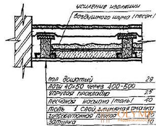
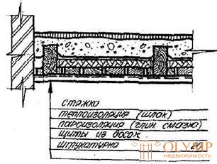
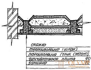
Overlaps on wooden beams (Fig. 47, 48.)
Tiled bars 40 to 50 are antiseptic and nailed to beams (or bars) with nails d = 4.5 mm, l = 125 mm, every 300 mm.
The dimensions of the cross-section of the beams depend on the magnitude of the load and span and are determined by their static calculation (or special tables). The ends of the beams mow down to increase the surface of evaporation of moisture from the beams and providing an air gap between the ends of the beam and the laying. The distance between the axes of the beams is taken from 600 - 1100 mm
The depth of the support of the ends of the beams in the nests of the stone walls must be at least 150 mm. The ends of the beams are antiseptic with a 3% sodium fluoride solution or coated with resin (except the butt). To isolate from masonry, the ends are wrapped with two layers of roofing material.
In stone buildings, the ends of the beams are to be anchored.
Bearing the ends of the beams on wooden walls (chopped or cobbled) are made by cuttings.
All wooden elements are made of conifers (pine, larch, spruce, etc.).
For the construction of wooden floors in sanitary units, beams are laid with solid flooring of grooved bars 50–60 mm thick, and a waterproofing carpet is glued to the flooring and a clean floor is laid on the carpet (mostly ceramic tiles on a layer of cement mortar reinforced with thin wire).
Sometimes, for better ventilation, beams are left open. All wooden elements are antiseptic.
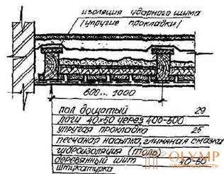
The feature of attic floors in the village. beams is the presence of insulation.
Sometimes, a vapor barrier made of coiled material is arranged under the plaster underneath the plaster, which prevents the wood from rotting when it is moistened during the cold season due to the penetration of water vapor from the upper floor.
In the industrial prefab construction for the girder filling, roll-ups of various materials are used, which are produced at the factory - gypsum-concrete slab of the bale or light concrete.
Advantages of wooden floors: simplicity of the device and low cost;
Disadvantages: flammability, the possibility of decay and relatively low strength.
Reinforced concrete floors
Reinforced concrete floors are prefabricated and monolithic.
Precast reinforced concrete floors.
They most satisfy the requirements of the complex mechanization of building construction, make it possible to reduce the complexity of work, drastically reduce construction time.
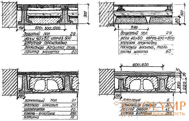
By the form of the main bearing elements, they are divided into beam and panel. Beam ceilings consist of beams, interblock filling and floor (fig. 49, 50.).
Beams are applied tavrovogo profile. The depth of bearing the ends of the beams on the walls or girders shall be at least 150 mm. To increase the stability of the walls, the ends of the beams on the supports are fixed with steel anchors.
Lightweight concrete double-hollow liners - made of concrete M = 75, are used in floors whose own weight and payload does not exceed 850 kg / m2.
Non-carrying plates of roll are made of gypsum concrete or lightweight concrete M = 75 and reinforced with a wooden rack frame.
Roll-up bearing plates are made of lightweight concrete M = 100, reinforced with welded and steel meshes. In rooms with high humidity (over 70%) they are not used.
When layout beams use templates.
These overlappings are distinguished by low weight of assembly elements; they are used in cases when the construction of individual buildings does not have powerful lifting and transport mechanisms.
The advantages are durability, non-combustibility, no need for wood, the possibility of using local materials.
Disadvantages: significant labor costs and the inevitability of wet processes in construction, as well as a relatively large own weight.
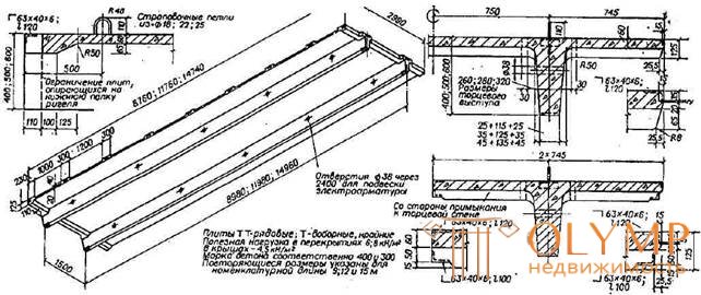
Pre-stressed reinforced concrete slab-2T slabs are made for spans of 9, 12 and 15 m. The width of TT-9 slab-flooring plates is 1.5 m; TT-12 and TT-15 - 3 m. The height of the longitudinal edges of the plates - decking TT-9 - 400 mm; TT-12 - 600 mm; TT-15 - 750mm. For spans of 18 m, the production of slabs - decking 2T wide 3 m with a height of longitudinal ribs 900mm. (fig. 58, 59.).
Panel coverings are divided into:
1. Overlap in the form of flooring, weighing up to 2 tons;
2. Large-panel floors of elements weighing up to 5 tons.
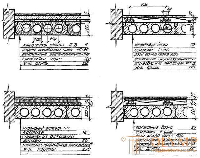
Decking in the form of flooring consists of flat or ribbed elements of the same type, laid close together and connected to each other by filling the gaps between them with cement mortar. Supports for decking are walls or girders (Fig. 51, 52, 53.).
These floors are more industrial than beamed and have a lower height.
Concrete floor slabs made of heavy concrete.
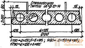
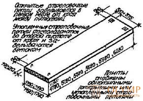
These plates are made with prestressed reinforcement. The length of the plates is from 3 to 7.2 m with a gradation of 600 mm, as well as 9 and 12 m. The width of plates up to 9m varies from 1.2m to 3.6m, with gradation through 600mm. The width of the plates 12m long is 1; 1.2; 1.5m The thickness of the plates up to 9m is equal to 220mm; for plates with a length of 12m - 300mm (Fig. 51, 52, 53).
Plates are laid close together and connected to each other by filling gaps between them with cement mortar. They rely on supporting walls or runs on two sides. The minimum support for brick walls is 120 mm, for block walls it is 100-110 mm, for panel walls - 70 mm. These slabs-flooring perform with round and oval voids.
Multi-hollow slabs of lightweight concrete used in buildings with a large step bearing walls (up to 7.2 m). Material - keramsit concrete, slag concrete.
Reinforced concrete slabs - solid made from heavy concrete. Their sizes accept multiple 300mm. The thickness of the plates 120, 140, 160, 180mm. Slabs with a thickness of 120 mm are used in panel buildings with a pitch of supporting transverse walls up to 3.6 m; make them the size of "on the room" sopiraniem on three or four sides of the plate.
The 140mm thick plates are supported both “along the contour” and on both sides (fig. 56).
Slabs with a thickness of 160, 180 mm are used at the steps of supporting transverse walls up to 4.8-6.0 m and are supported on two sides.
A uniform system of channels for electrical wiring, openings for the passage of vertical communications, pipelines and ventilation devices is provided in the floor slabs, as well as fixtures and fittings for connecting with adjacent structures are provided (Fig. 57).
Monolithic reinforced concrete floors.
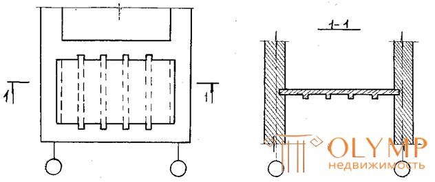
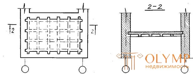
Monolithic reinforced concrete floors consist of a flat plate supported on walls and a system of beams (ribbed and coffered floors) or on walls and directly on columns (non-beam floors).
Ribbed floors are a structure consisting of interconnected slabs and beams. The span of the slab (the distance between the axes of the ribs) takes from 1.5 to 3.0 m, thickness from 60 to 100 mm.
Beams (or edges), as a rule, are directed downwards, but if it is necessary to have a smooth ceiling, they can be positioned on top.
Caisson overlap is obtained by intersecting evenly spaced edges of the same height; it is used for aesthetic reasons in the interiors of public buildings, and also as a means of alleviating a large mass of the slab with large spans.
Frameless ceilings are supported by columns, through wide capitals.
The listed overlappings are made at a construction site in a specially made formwork.
Recently, instead of monolithic structures, promising constructive building systems of prefabricated monolithic buildings erected in the “Grazhdanstroy” type formwork have been used.
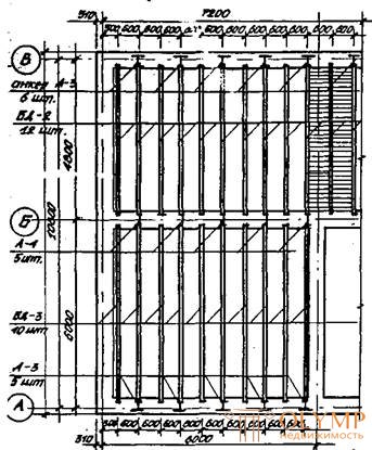
CLOSING PLAN
BETWEEN COVERS ON WOODEN BEAMS WITH NAKATA SHEETS

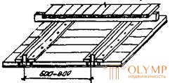
1- clean floor; 2 - lag; 3 - plaster;
4 - beam; 5 - cranial bars; 6 - roll up shield; 7 - sound insulation (backfilling)
FINISHING OF THE END OF WOODEN BEAMS
AT THE DEAF DEAL IN OUTSIDE WALLS
WITH OPEN DEAL IN EXTERNAL WALLS


WITH AN OPEN LOCK IN THE INTERNAL WALLS

1 - grouting; 2 - two layers of roofing paper on mastic; 3 - anchor; 4 - nails; 5 - open nest; 6 - 50x6 mm pad
WOODEN BEAMS WITH SKULL BARS
NAKATA SHIRT DESIGN
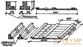
FINISHING OF THE END OF WOODEN BEAMS
WOODEN COVERAGE IN SANITARY UNITS
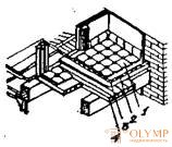
1 - ceramic plates; 2 - cement mortar; 3 - waterproofing; 4 - flooring of grooved bars 50 - 60 mm
BETWEEN COVERS
ON WOODEN BEAMS AND NAKATA PLATES FROM EMPTY POWERED CONCRETE BLOCKS
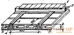
1– clean floor; 2 - lag; 3 - plaster or grout; 4 - roll up shield; 5 - solution; 6 - light concrete block
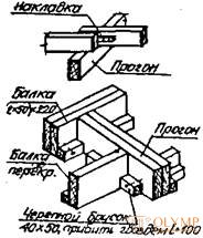
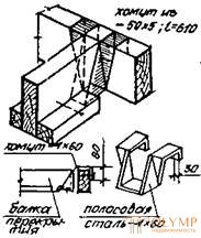
Fig. 47
BETWEEN COVERS
FROM WOODEN SHIELDS
FROM PLATE CONSTRUCTION PLATES
ATTIC BLOCKS
INSTALLATION OF PARTITIONS 2nd FLOOR
PARTITIONAL PARTITION
INTERNAL PARTITIONAL PARTITION
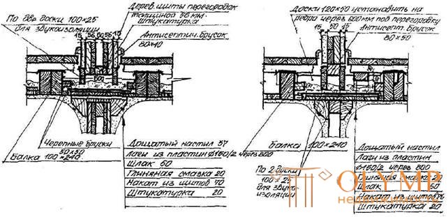
Fig. 48.
CLOSING PLAN
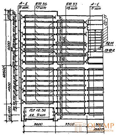
BETWEEN COVERS
ON REINFORCED CONCRETE BEAMS WITH ROLLS FROM CONCRETE PLATES
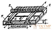
1 - clean floor; 2- lag; 3 - plaster or grout; 4 - reinforced concrete beam; 5 - gypsum concrete slab;
6 - solution
BETWEEN COVERS
BULKING
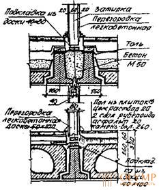
SECTIONS
BEAM OF TAMPER SECTION
PLATE NAKATA LIGHT-CONCRETE
STONE - INSERT

ANCHORING AND BEAMING
INTERNAL WALL

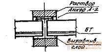
NOTES:
OUTER WALL
1. Reinforced concrete T-beams (BT) to take the same section C ( h = 220) with a length of not more than 6000 mm and a multiple of 300mm .;
2. Slabs of (non-bearing ) run-up - gypsum-concrete 395x80 ( h ) unreinforced; carrier - 395x90 ( h ) reinforced (for the attic floor);
3. Anchoring of beams is carried out in 1 - 2 pieces.
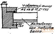
Fig. 49.
BETWEEN COVERS
FLOOR (PLEASED, PARQUET, LINOLEUM)
RESIDENTIAL ROOM
FLOOR CERAMIC TILES
(IN SANITARY UNITS)

ATTIC BLOCKS

Fig. 50.
BETWEEN COVERS
FLOOR (PLEASED, PARQUET, LINOLEUM)
RESIDENTIAL ROOM
COVERINGS IN SAN. UNITS FROM CERAMIC TILES
ATTIC BLOCKS
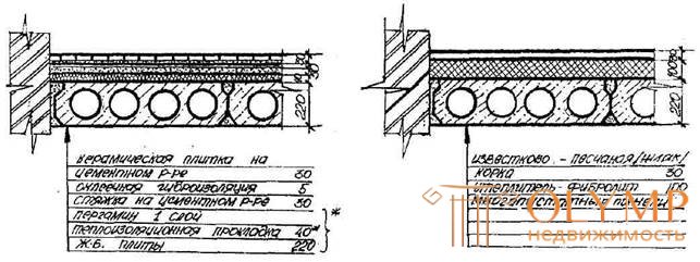
* denotes the components and dimensions of the overlap above the cold basement
Fig.53.
CLOSING PLAN
BUILDINGS WITH LONG-TERM WALLS
PAINTING ON A BRICK WALL AND DETAILS OF ANCHORING
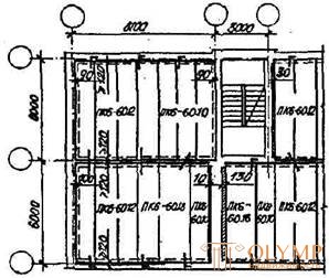
DECODING MARKING PLATES:
P - stove; K - with round voids; 4; 6; 8; 10 - design load; 4; 6; 8 and 10 kN / m2 (excluding the plate's own weight);
60.12 - length and width in dm.
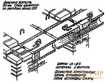
ADDITION TO A BRICK WALL (BASIC - WITH A DEPARTURE IN A DEPARTURE)

SECTION OF PLATE WITH ROUND VOLUMES
SEAMS BETWEEN PLATES

PEELING AND FASTENING ON EXTERNAL WALLS
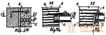
DESIGN AND FASTENING OF PLATES ON INTERNAL WALLS
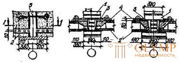
1 - wall; 2 - overlap; 3 - steel anchor; 4 - cement - sand mortar; 5 - concrete grade M 200; 6 - reinforced concrete
Fig. 51.
MOLDING OF MULTIPLAYER WALL CLOSING PANELS
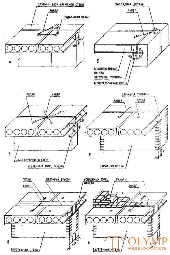
a, b - external large-block; in - internal large-block; G - exterior brick; d - internal brick; e - the same with channels
Fig. 52.
COVERINGS OF LARGE PANEL BUILDINGS AND THEIR DETAILS
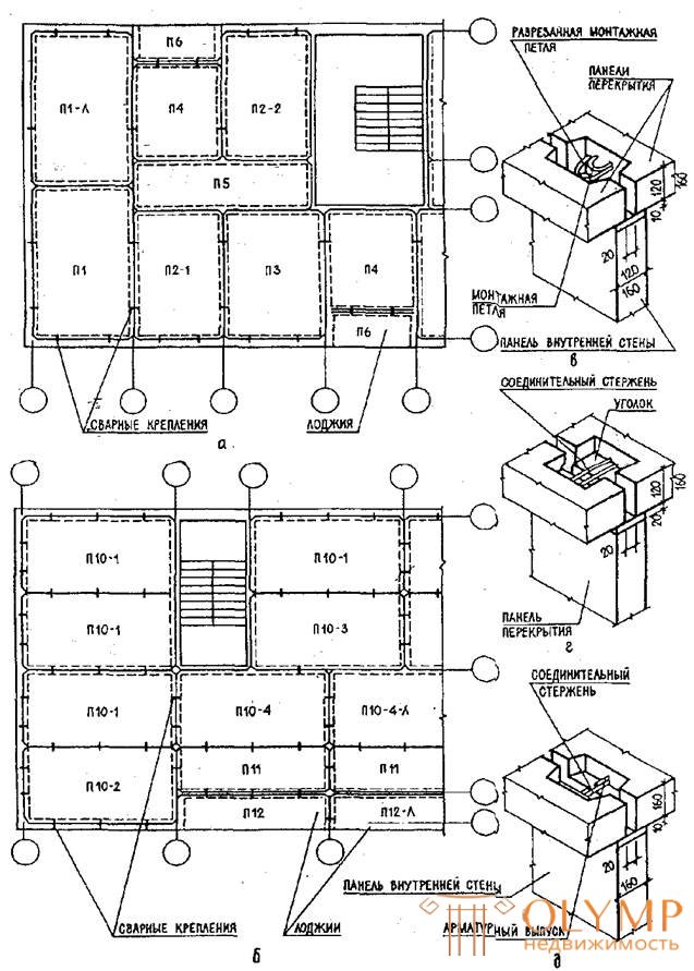
a , b, - wiring diagrams of overlapping at small (a) and large stride walls (b); в - joint and fastening of the ceiling panels by welding the hinges between each other when supported by the internal walls; g, d - the same with connecting rods
Fig. 54.
CONTINUOUS REINFORCED CONCRETE PANELS OF OVERLAPPING OF LARGE PANEL BUILDINGS
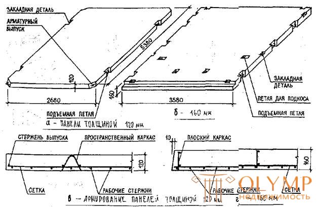
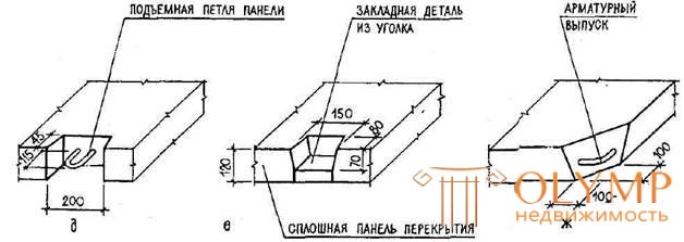
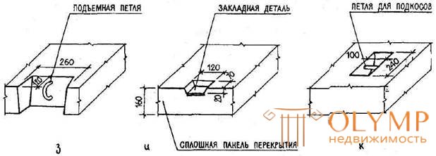
a , h - lifting loops; e, and - embedded parts for welded fastenings of panels; W = reinforcement in the corner of the panel; k = loop fastening mounting braces.
Fig. 55.
FLOOR CONCRETE FLATING PLATES FOR RESIDENTIAL BUILDINGS WITH SMALL (2.7 ÷ 3.6 m) STEP OF BEARING WALLS (SERIES 1.143-2)
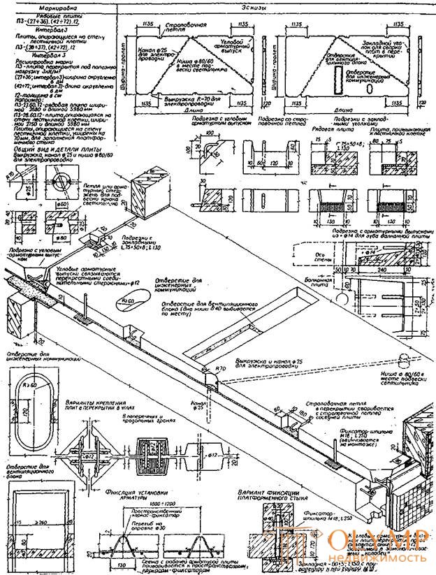
Fig. 56.
FLOOR CONCRETE FLATING PLATES FOR RESIDENTIAL BUILDINGS WITH A BIG (≤6.3m) STEP OF CARRYING WALLS (ON SERIES 108)
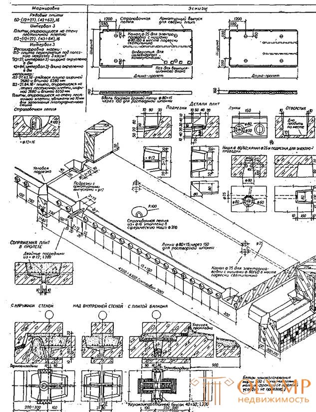
Fig. 56.
RIBBED, PRE-STRESSED, PADDED
9 M SPAY

PRELIMINARY STRESSED MESTERED
TYPE TT-12 (12M) TT-15 (15M)
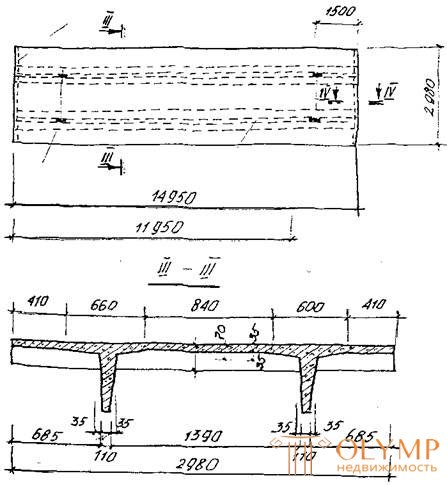
1 - mounting hinges; 2 - longitudinal ribs; 3 - transverse ribs
Fig. 58.
REINFORCED CONCRETE SHEET PLATES OF TT- AND T-SECTION FOR STEP OF WALLS TO 15 M (SERIES 1.242-1)
USED IN OVERLAPES AND ROOFS OF PUBLIC BUILDINGS
CERAMZY CONCRETE VENTILATED PLATES FOR COMBINED ROOF WITH EXTERNAL WATER DRAIN
With longitudinal channels Ø60;
VIA 165 (SERIES 1.165-2)
WITH TRANSVERSE CHANNELS 50x50 / 2;
Through 250
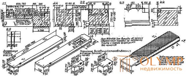
CERAMZY CONCRETE PLATES (SERIES 1.165-7) FOR COMBINED ROOFS WITH AN INTERNAL WATER
PARAPETON PLATES
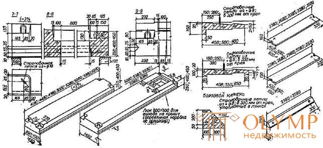
Fig. 59.
MONOLITHIC REINFORCED CONCRETE LINES
BALOCHNY
CAPSON
UNCOMBODIES
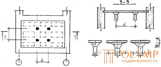
Fig. 60
Что бы оставить комментарий войдите
Комментарии (0)