The scope and composition of the field work depends on the tasks solved during engineering geological surveys and is carried out on the basis of the program. Works include surveys, inpatient observations and experimental work.
Geophysical work
Geophysical methods are used in engineering and geological studies of the composition and properties of rocks and geological phenomena, as a rule, in engineering and geological surveys. The most widely used in the practice of exploration found the following methods: electrical, seismic, radiation, magnetic, thermometric.
Geophysical methods significantly accelerate and improve the quality and accuracy of engineering and geological surveys. These methods are used to study in vivo the processes and phenomena occurring in rocks, as well as to study the physico-mechanical properties of rocks, the distribution of these properties in space and their changes over time.
The electrician is based on the study of the conditions for the passage of electric current in various soils. In this case, either natural or artificial electromagnetic fields are used. Since one of the main parameters of a rock is its electrical resistivity, by measuring it, a geoelectric section can be obtained, which has a direct one-to-one connection with the geological one.
Using electrical prospecting, a geological section is refined when taking photographs, determining the thickness of aquifers and the depth of reservoirs, the thickness of the weathered zone of rocks, the position of ancient river valleys, cavities and craters in karst rocks, establish the position of fractured zones and tectonic faults, determine the boundaries and properties of multiyear rocks. frozen rocks.
This is based on observations of the speed of propagation of elastic waves in the earth's crust, caused by artificial tremors (explosions, impacts). As a result of an explosion in the ground, elastic waves arise - longitudinal and transverse. The speed of propagation of elastic waves in soils depends on their mineral composition, structure, fracturing, humidity, etc. In sands, for example, the speed ranges from 0.2 to 1.5 km / s, in clays 1-3 km / s, in limestone 3-6 km / s, in a wet rock the speed is greater than in dry rock. The nature and speed of propagation of elastic waves is observed on the surface of the earth by special instruments - geophones, located along straight lines - profiles. If the profile line passes through the point of explosion, then the profile is called longitudinal if it is arbitrarily relative to it — transverse.
The use of the method of engineering and geological research in engineering and geological research is based on measuring the intensity of natural and artificial radiations. To study such important properties of rocks as humidity and density, radiation methods are used, based on measuring the absorption capacity of rocks during the passage of various radiations.
Magnetic methods are based on measuring the features of the Earth’s magnetic field and the magnetic properties of rocks. The magnetic properties of rock massifs change dramatically in the zones of tectonic faults and fracturing, as well as in the zones of geodynamic instability of rocks. According to magnetic intelligence data, the genesis and composition of rocks are established.
Thermometric methods are widely used in the study of cryogenic physical-geological processes and phenomena in permafrost areas.
In practice, engineering surveys to solve practical problems of engineering geology often have to use several fundamentally different geophysical methods. The use of a complex of geophysical methods is a very effective means for uniquely solving problems of studying rock properties and engineering-geological processes. Currently, there is an intensive development and introduction of geophysical methods into the practice of engineering geological surveys and studies.
Monitoring the groundwater regime, the development of engineering and geological processes
The products are the most important element of the geotechnical conditions of a territory. In the design and construction of facilities, the rational use of territories, geological environment, groundwater always have not only engineering and geological significance. Therefore, it is so necessary to study groundwater - their distribution, occurrence conditions, hydraulic features, feeding and unloading conditions, reserves (resources), regime, etc. Stationary observations are carried out at the stage of engineering and geological surveying and exploration to study:
- groundwater level positions;
- conditions of groundwater supply and their reserves (resources);
- connections of groundwater with surface waters and dependence of the regime of the former on the regime of the latter;
- interrelations between separate horizons and zones of groundwater, the availability and reliability of water stubs, both local and regional;
- changes in the regime of groundwater (levels, resources, chemistry, etc.) under the influence of existing reservoirs, the operation of structures and other factors;
- the influence of the groundwater regime on the development of geological processes and phenomena (flooding and waterlogging of territories, salinization of rocks, development of landslide and subsidence phenomena, changes in microseismic conditions, etc.).
The depth of occurrence is determined with the help of special tools (Fig. 2.2). For the chemical analysis of water in laboratory conditions, samples are taken from wells, and from different depths.
The depth and thickness of the aquifer free-flow reservoir are determined by measuring distances from the wellhead to the aquifer mirror and from the groundwater mirror to the roof of the impermeable formation. In a pressure aquifer, the thickness of the horizon is determined by the distance between the upper and lower reservoirs.
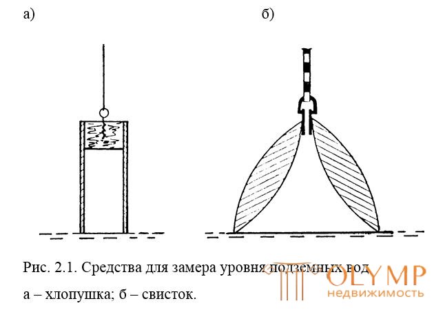
Fig. 2.1. Means for measuring the level of groundwater
a - crackers; b - whistle.
The information obtained makes it possible: to reasonably evaluate the geotechnical conditions of the territory; to determine the conditions for the production of construction and mining works, the conditions for the operation of structures, the aggressive effect of water on the underground parts of structures, etc. to develop measures to combat the flooding of the territories, with water inflows during the excavation of pits and underground workings, etc .; develop measures for the protection of the geological environment.
And z ucheni f and z and k about-go to about the about go to and with with to and x p pro about c with - with about about in. The main purpose of studying physical and geological processes and phenomena is to assess the degree of their influence and to choose ways of dealing with their adverse effects on the designed structures. To achieve this goal, the conditions and patterns of development of processes and phenomena must be studied, i.e. their types and their association with certain types of soils, elements and forms of relief, hydrogeological and cryogenic conditions are revealed.
The formation and development of physical and geological processes and phenomena are usually influenced by several natural factors. Some of them create conditions for their occurrence, some contribute to the revitalization of their development. Among these factors, geological and climatic factors are decisive, the interaction of which determines the type of process and the nature of its manifestation. The following physical-geological processes and phenomena do not cover all their diversity, but are listed as the most frequently encountered. These are: eluvio formation, freezing and thawing, landslides and debris, avalanches, landslides, frost and ice mounds, sweeping and winding phenomena, solifluction, soil erosion, washing away of banks, gullying, erosion of slopes, mudflows, lake and erosion, and coastal mud. sedimentation of reservoirs, suffosion and seepage deformations of the surface, karst phenomena, seismic phenomena, rock pressure, subsidence in loess-like rocks and loess, shrinkage, displacement of rocks in undermined areas, etc.
Most often, during engineering and geological surveys, one encounters manifestations of various kinds of processes occurring on slopes (landslides, landslides, talus, kurums), karst manifestations, revealing mudflow danger in areas, etc.
When describing gravitational processes on slopes, it is necessary to adhere to the following schemes.
P about b in and l and m:
separation area - height, genesis, age of the slopes; conditions of occurrence and the basic properties of rocks that form the slope; slope shape;
transit area - the length of the path, the relative height of the fall, the morphology of the path of motion, traces of motion;
deposition area - a characteristic of the place of deposition; approximate amount of collapsed mass and its morphology; approximate definition of the approximate date of collapse; shape # lyub collapsed mass, especially sorting, range of fall and the size of individual blocks; damage or disturbance caused in the area of collapse;
statistical information about the collapse of the area of the survey and information about the presence and nature of the anti-tailings facilities, as well as their effectiveness.
P o about s s p I m:
the area of separation and the process of shedding - the morphometric characteristic of the slope, its exposure; the position, shape and size of the nutrition area of the talus; composition and basic properties of the rocks forming the area of feeding (occurrence conditions, fracturing, weathering); size, shape of debris, the nature of their movement (sliding, rolling); the presence of sites, indicating the termination of the process;
accumulation area - conditions of occurrence of debris, its morphology; dimensions and signs of sorting material scree, the presence or absence of aggregate and its composition; watering conditions for debris, sources of watering and its signs; the presence of vegetation on the body of debris and other signs that allow to assess the age and degree of its mobility.
P o o p o l zn m:
the slope or slope on which the landslide occurred - the location, exposure, genesis, age, morphometric and morphological characteristics, the geological structure of the slope (slope) and its base, the state of the rocks forming the slope; hydrogeological conditions of the slope; the presence of natural and artificial disturbances on the slope, behind the ridge and at its foot, for the slopes - the time and method of construction;
the landslide characteristic is the breakdown position, the presence and dimensions of the extrusion shaft; hydrogeological conditions of the landslide body, the presence and intensity of water manifestation; assessment of the power of the landslide body and the dynamics of movement of the material of the landslide body; the state of vegetation, structures, the presence and nature of the manifestations of deformation of structures; the age of the landslide, the ratio of landslides of different ages and the ratio of the described landslide with neighboring landslides; information about the dynamics of the landslide, in the presence of observations, or on survey data; information about landslide activities; conclusions - the type of landslide and its causes, the relative importance of various factors in the formation of a landslide; the interrelation of the processes occurring on the landslide slope, the development stage of the landslide and the forecast of the further development of the landslide process.
K a r with t is usually typed by the composition of karsting rocks, by their occurrence relative to the earth's surface and relative to the regional groundwater level.
In zones of wedging out of groundwater in natural or artificial slopes, the removal of small particles of soil is sometimes observed, the phenomenon of discharging the lower parts of the slope and the formation of craters above the edge of the craters, in some cases turning into gullies and ravines. These phenomena are associated with the filtration destruction of soils. Among the soils prone to filtration destruction, can be called fine and fine-grained, micaceous and loose sand, as well as powdered-clay non-water-resistant rocks such as loess and loess loam. In natural and artificially created conditions (dredging on slopes, pits, quarries), two types of seepage destruction of soils can be observed — spilling and colloid mechanical suffusion.
Bleeding occurs under the action of the filtration pressure of the underground flow, when the resistance force in the soil (internal friction and adhesion) is less than this pressure, defined as the product of the density of underground water and the filtration gradient of the underground flow.
Colloidal mechanical suffusion is the removal of small and colloidal soil particles by the flow of groundwater. This process is called internal erosion.
Drilling and mining operations
Mine workings
Open mine workings are clearing, digging, pits, ditches, mines, adits. The advantage of these workings over wells is that you can directly see the nature of the bedding, select structurally undisturbed rock samples, and test them under natural conditions.
Consider the main types of mine workings.
R and with h and with since a - one of the most simple and easy-to-work workings carried out in places of natural outcrops and steep slopes of relief, when for opening rocks it is enough to remove (throw down) a small layer of soil, depletion or debris from the slope. Rock samples are taken from the clearing for laboratory research and the construction of a geological section.
Zakopuzhka is a small funnel development with a diameter of about 0.3 m and a depth of 0.5 ... 0.8 m, which is performed to expose the rocks (bedrock) lying under the soil layer or layer of surface sediments. Zakopushki find the greatest application at engineering and geological shooting.
W y p f - vertical mine workings with a cross section of about 1.25 x 1.5 m and a depth of 20 m or more. Round holes are called d u dk a m i. Holes are in dry, loose horizontal or slightly inclined seams. With great depth and with the passage of aquifers, the walls of the hole strengthen. Recently, special machines have emerged, which are miner diggers, which speed up and greatly facilitate the digging of holes. The hole provides an opportunity to inspect, photograph, sketching the bedding, take samples of rocks for laboratory research, and carry out field tests. The beddings of rocks found in the hole are usually represented as a sweep of its side walls and bottom.
K and NAVA - development of a trapezoidal section with a base width of about 0.6 m, a depth of 3 m and a length of up to 100 ... 150 m. It is advisable to tear ditches in steeply dipping seams and set the direction of the formations across them; they can be torn off manually and with the help of earthmoving machines. Using the ditches, the geologist can get about the same information as in the pits of the Fig. 2.2.
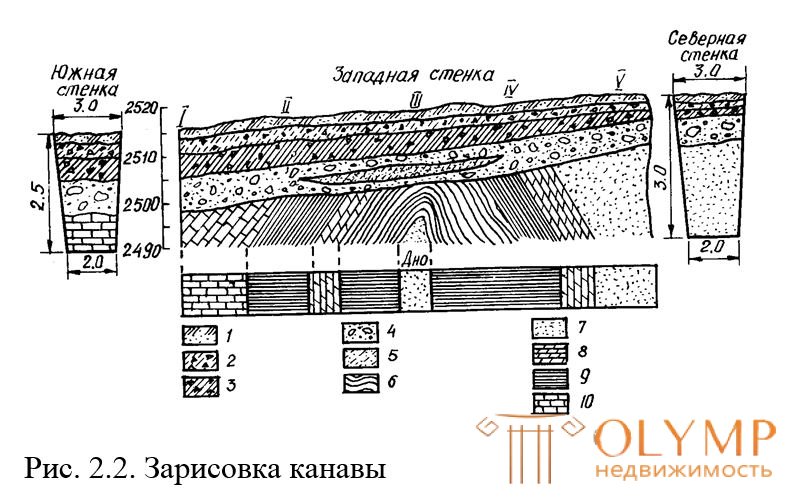
Fig. 2.2. Ditch drawing
IV - point numbers; 1 - plant layer; 2 - sandy loam with rubble;
3 - loam with rubble; 4 - sand with boulders and pebbles;
5 - sand strongly clay; 6 - slates; 7 - fine micronized sand; 8 - dolomites; 9 - clay; 10 - limestone.
The shh t a - vertical generation of a section of 22 or 23 m and a depth of up to 100 m. The purpose of the mine is the same as the hole, but the mines, because of their high cost, are held only at critical structures and in difficult geological conditions.
Shtolnyi - horizontal generation of trapezoidal section, about 1.8 m high, 1.3 meters wide at the base 1.7 m, and 1 m high at the top, having access to the day surface. Adits are usually arranged in the coastal slopes of rivers, along the strike or across the strike of the seam. This type of mine workings is intended for solving various tasks, in particular in hydraulic engineering, to determine the fracturing and filtration properties of soils in the coastal sections of the dam; for the detection of suffusion processes. In the galleries, in the presence of reliable soils, land surveyors lay reference height ramps. The absence of abrupt temperature changes in the adit (entrance to the adit is closed by a door) ensures high stability of elevations of elevations.
Drilling operations
Drilling wells, will be performed to study the geological section, i.e. to identify the sequence of occurrence of layers, their thickness, composition, density, consistency, humidity, water flow, as well as for sampling of rocks and subsequent testing in laboratory conditions. Manual and mechanical drilling is used for this purpose. Manual drilling is carried out by a rotary percussion or percussion cable method. Mechanical drilling is carried out by rotational, shock-mechanical and vibro-drilling installations.
The choice of drilling method depends on the composition of the rocks being passed, on the purpose and depth of drilling, on the conditions of work. When choosing a drilling method, special attention is paid to the quality and type of samples of rocks selected and the economic efficiency of the method.
The diameters of wells depend on their purpose and vary widely - from 89 to 325 mm or more, and the depth of engineering and geological wells may be 10, 30, 100 m and more.
Способ ручного бурения применяется на объектах с малыми объемами работ, в районах, куда доставка механических буровых установок может быть сопряжена с трудностями. По способу проходки скважины оно может быть вращательным, ударным и комбинированным - ударно-вращательным. Для взятия образцов породы с ненарушенной структурой используют грунтоносы. Ручное ударно-вращательное бурение применяется для всех видов грунтов, кроме скальных; бурение ведется с применением разного рода средств и приспособлений, рис. 2.3.
В зависимости от состава пород в глинистых, суглинистых и песчаных грунтах применяют ложки и змеевики, в обломочных породах - долота и желонки, в сильно обводненных песчаных и илистых грунтах - желонки. В процессе ручного бурения производится отбор образцов грунта нарушенной и не нарушенной структуры.
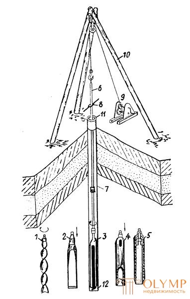
Fig. 2.3. Ручное бурение
1 - змеевик; 2 - долото; 3 - ложка; 4 - желонка; 5 - грунтонос;
6 - штанга; 7 - обсадная труба; 8 - хомут; 9 - лебедка; 10 - копер; 11 - устье скважины; 12 - забой.
На основании механизации ударно-вращательного способа возник ударно-канатный способ бурения. Буровой снаряд, спущенный в скважину на канате, периодически поднимают и сбрасывают на забой с помощью ударного механизма рис. 2.4. Бурение у д а р н о-к а н а т н ы м способом может вестись сплошным и кольцевым забоем. При бурении сплошным забоем проходка скважины производится путем сбрасывания (ударов) на забой долота, с последующим извлечением породы желонкой, а при бурении кольцевым забоем - сбрасыванием (забивкой) забивного стакана, который постепенно наполняется грунтом и затем поднимается на поверхность. Долото используют для раздробления твердых включений (валунов и др.). Желонка представляет собой стакан, в нижней части которого имеется башмачок с клапаном, который при подъеме закрывает отверстие. Недостаток этого способа бурения - его большая трудоемкость и малый темп работ.
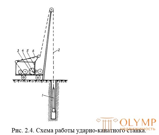
Fig. 2.4. Схема работы ударно-канатного станка.
1 - буровой снаряд; 2 - инструментальный канат; 3 - шестерня привода ударного вала; 4 - кривошип; 5 - шатун; 6 - оттяжная рама.
К о л о н к о в о е бурение является разновидностью вращательного способа проходки скважин, когда забой разрабатывается по кольцу, с оставлением не разрушенного столбика породы-керна, рис. 2.5. Его основные преимущества:
1) получение образцов в виде колонки породы-керна, по которому судят о геологическом строении и физико-механических свойствах проходимых пород;
2) возможность бурения скважин в породах любой крепости под различными углами наклона к горизонту.
Core drilling is carried out using a core pipe, to the lower end of which an annular crown with hard alloy teeth or a diamond crown is screwed, which rotates at a speed of 50-300 rpm to form a bottom in the form of a ring, and a column of untouched rock remains in the center - a core . The products of rock destruction — sludge — are removed from the face (depending on the physicomechanical properties of the rocks and the depth of the well) by injecting mud into the well or purging with compressed air. When the core pipe is filled with a core or when the crown incisors are blunt, drilling is stopped; the core is wedged in the cone of the crown body, torn from the bottom and lifted along with the projectile to the surface. Core drilling can be used for drilling wells in all types of soils (with the exception of sandy and clayey soft-plastic)and at considerable depths. This method provides samples of rocks (core) with a natural structure and humidity.
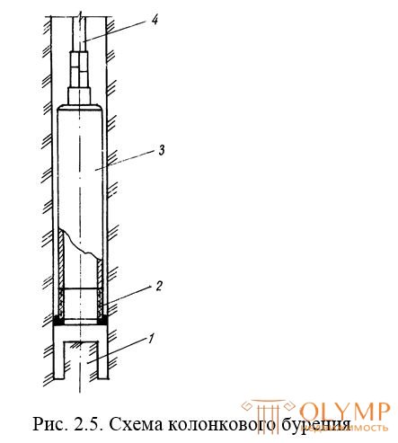
Fig. 2.5. Core drilling pattern
1 - core; 2 - crown; 3 - core pipe; 4 - bored pipes.
For sampling in weak rocks, a so-called double core tube is used, consisting of two tubes connected by a ball bearing device. During drilling, the inner tube does not rotate and does not allow the rock that fills it to collapse.
Core drilling has a great advantage over other drilling methods. The recoverable cores can restore the character of the rocks in the array - their layering, composition, fracturing, voids, intermittent bedding, the slope of the layers, as well as the sliding surface in the landslide body, etc.
As well as core drilling, this is a category of rotational drilling methods, but can only be used for drilling in clay, loam, silt, and clayey sandy loam. The destruction of rocks during auger drilling is performed by two- or three-fold stepped bits, which are connected to the auger with the help of quick-release locks. The screw is a pipe on which a helix made of steel tape is welded along a helix with a pitch of 0.6 ... 0.8 m from its diameter, fig. 2.6. This method is characterized by high performance, since the drilling process and the lifting of the soil occur simultaneously and continuously, and the cost of auxiliary operations (descent and lifting of equipment) are minimal. The depth of drilling in this way usually does not exceed 30 m, but sometimes 100 m (hydrogeological wells). When the screw method of drilling poorly defined boundaries of individual layers; the structure of the soil leaving the well is disturbed; groundwater levels are difficult to determine. In connection with these shortcomings, it is advisable to use the screw method to test a previously established geological section. Due to its high performance, the screw drilling method can be successfully applied when laying out geodesic centers and benchmarks, especially in the conditions of construction sites, where a lot of geodetic signs can be located on a relatively small area.
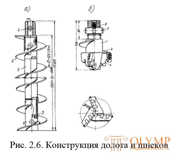
Fig. 2.6. Chisel and screw design
a - auger (UGB-50A installation): 1 - pipe; 2 - spiral; 3 - sleeve; 4 - shank; 5 - connecting finger; 6 - retainer;
b - three-chisel chisel: 1 - case; 2 - spiral; 3 - the blade;
4 - cutter.
V and br and c and about N of the N of b e is based on penetration of a ring tip - a vibrosonde into a rock. Vibration probe is a pipe with a diameter of 40 ... 200 mm, length 0.5 ... 3 m; along the entire length of the pipe has one or more slots for cleaning the probe from the rock; the lower end of the pipe is provided with a ring with a sharp cutting edge. The introduction of such a tip into the ground is due to the fact that under the action of the vibration of the probe the frontal and lateral resistance of the soil weakens to a very strong degree and the probe under the action of its own weight and the weight of the vibrator sinks into the soil. As a downhole tool, a grouser can also be used - for obtaining soil samples of a structure that is not disturbed and the shell - for penetrating loosely bound loose rocks, silts and water-saturated rocks. Vibration drilling is a promising method, it has high productivity, it can be used when sinking clay, loam, sandy loam, sand, gravel-pebble soils. The most favorable depth of drilling in this way is 15-20 m. The vibro-method makes it possible to select soil samples with undisturbed structure, but makes it difficult to fix the level of groundwater.
Selection, packaging and transportation of rock samples
The reliability of the results of laboratory studies of the physicomechanical properties of rocks depends on the correctness of sampling, preservation in the process of selection, transportation and storage, as well as on the natural composition, structure of the rock, its natural moisture content and particle size distribution.
Rock samples are taken undisturbed or disturbed addition, but with the obligatory preservation of the natural grain composition. Samples with undisturbed addition - M o n o l and t s - should have orientation (bottom - top of the monolith). During the selection of the monolith is not allowed violation of the natural composition of the soil.
Soil samples, in particular, are taken from mine workings with a knife, blade, etc., as well as from wells with the help of drill bits or submersibles. When sampling rocks that require the preservation of natural moisture, drilling of wells is performed without the use of drilling fluid and without pouring water into them, with a reduced number of revolutions of the drill bit or submersible.
The selection of monoliths from the mine workings is made in the form of a piece of rock, from which samples of the required size are cut out.
The method of selection of monoliths from boreholes depends on the type of soil and its condition. So, monoliths of sandy rocks, clay rocks of solid and semi-solid consistency, dense ground soil with plant roots are selected with the help of obburivayuschih gribosny, groundwater that has an internal non-rotating (soil receiving) sleeve. Clay rocks of semi-solid and refractory consistency are selected using thin-walled cylindrical submersibles with a pointed lower edge, immersed by the indentation method at a speed of not more than 2 m / min.
Loose sandy rocks, clay rocks of a soft-plastic, fluid-plastic and flowing consistency, decomposed peat are selected using soil feeders with an overlapping inlet, immersed by the indentation method, with a speed of not more than 0.5 m / min.
Monolith after paraffin waxing. To do this, it is tightly wrapped with a layer of gauze, pre-soaked in molten paraffin, mixed with tar. Then the whole monolith in gauze is covered with a layer of paraffin, wrapped with a second layer of gauze. On the upper surface of the monolith stack label.
Monoliths of non-frozen rock, packed in boxes, are transported at a positive ambient temperature, and monoliths are frozen at a negative temperature or by transport equipped with a refrigerating chamber, in which the negative temperature is maintained.
Experienced field work
To obtain reliable characteristics of the physicomechanical properties of soils along with laboratory methods, soils are tested directly in an array at the site of future construction. Currently, for these purposes, the following methods are used:
- method of static loads on dies;
- pressometry;
- cut pillars in the mine workings, crushing, bulging, collapse; rotational cut impeller;
- static and dynamic sounding;
- soil testing with inventory piles and testing of experienced full-size piles;
- determination of the type of ground conditions by subsidence by experienced soaking.
In the course of field work, hydrogeological parameters are determined, in particular: the filtration coefficient, the thickness of aquifers, the chemistry (chemical composition of groundwater), the direction and slope of the subsurface flow.
Field methods for studying soils are mainly used for particularly important structures and in the final stages of design, when there is already a complete picture of the geological structure of the site, there are geological sections, data on the physicomechanical properties of soils, and the general plan of the structure.
The most important characteristics of the soils, determined during field tests and necessary for the calculation of the foundation of the structure, are soil compressibility and shear resistance.
The compressibility of the soil is characterized by the modulus of deformation and Poisson’s ratio, and the resistance of soils to shear — the angle of internal friction and specific adhesion.
In field studies, the modulus of soil deformation can be determined by testing the soil with static loads (stamp) and a pressiometer.
The purpose of soil testing with static loads (punch) is to obtain reliable information on soil compressibility (deformation modulus) in a layer with a depth equal to one and a half punch width. In subsidence soils is determined by the additional amount of precipitation - subsidence, which occurs when they are wetted.
Tests by stamps are performed in pits and wells.
The dies consist of thick metal plates (reinforced with stiffeners) square - with an area of 5000 cm with a side of 0.71 m or round with the same area with a diameter of 0.8 m. For testing in wells, dies with a diameter of not more than 0.6 m are used. The plan must be at least 1.5 x 1.5 m, the minimum diameter of the well is 0.325 m. To ensure an underground contact of the stamp with the ground over the entire area, a screw-in stamp is sometimes used.
A uniform pressure is transmitted to the stamp in steps of 0.01 ... 0.1 MPa. Each step is kept until the precipitation stabilizes. The total number of steps must be at least four. Test mode is regulated in detail by the instructions and DSTU. The value of the modulus of soil deformation is obtained for selected pressure ranges depending on the magnitude of the increment of sediment.
The main elements of the equipment for field testing of soils with static loads are shown in Fig. 2.7: 1 - stamp;
a) b)
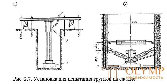
Fig. 2.7. Installation for testing soils for compression:
and - with a beam and anchor piles; b - with emphasis in the walls of the hole.
2 - installation for loading the stamp in the form of a platform or a hydraulic jack. The kit also includes defibomers - instruments for recording precipitation with an accuracy of 0.1 mm and other additional equipment.
And with p and t and n and with a p m about shchu yu p re with with and m et r a. The device consists of a cylindrical rubber hermetic chamber, which is lowered into the drilled well (Fig. 2.8) to a depth where it is necessary to determine the compressibility indicators of the soil. Then, internal pressure is created in the chamber using special hydraulic or pneumatic systems. The shell of the chamber tightly pressed against the walls of the well and begins to expand the latter, deforming the soil. On the surface of the earth are the equipment for creating and measuring the pressure in the chamber and instruments that record the deformation of the soil. The values of the modulus of deformation are determined by the amount of deformation of the soil at the appropriate pressure.
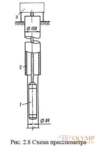
Fig. 2.8 diagram of the pressure meter
1 - probe; 2 - casing; 3 - measuring equipment.
And from the experience of this and that, the units are of particular importance for the places where the construction of structures with a certain tendency to shift, for example, bridges, dams, are being designed. However, shear tests can be carried out simply to obtain a more complete strength characteristic of soils that are not uniform in composition, tests of which under laboratory conditions do not give satisfactory results (content of heterogeneous inclusions).
Shear rock testing can be conducted in pits and wells. There are four test methods in pits: crushing a four-sided prism or a soil cylinder with a vertical load, shifting the rear sight along a predetermined horizontal plane, pulling the triangular prism to the side, collapsing the triangular prism down (Fig. 2.9 a, b, c ). Knowing the breaking force and shear surface area, the strength of the soil is calculated .
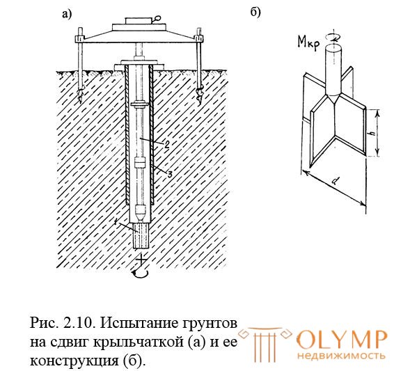
Soil shear tests can also be conducted in wells with paddle impellers (Fig. 2.10). For this, a two- or four-blade impeller 1, mounted on the rod 2 , is pressed into the bottom hole below the edge of the casing 3 . At the top, rotating the core of the rods with spacer plates of the impeller creates lateral pressure on the ground and then the impeller rotates.
This test method is based on measuring the limiting torque at which the shift (rotation) of the impeller blades begins. The shear resistance depends on the properties of the soil and the size of the impeller blades. Measuring the shear resistance at different pressures to the cut surface and knowing the dimensions of the impeller, we can calculate the indicators of strength properties
soils.
Such tests for one layer of rock are repeated in one well several times, gradually deepening the well.
Soil tests using paddle instruments can be conducted to a depth of 15–20 m. Paddle instruments can indirectly determine the modulus of soil deformation.
D and n and c e k o e z o n d e r a n i n is to determine the resistance that the soil has to the driving rod into it with a special steel tip screwed on it - a probe in the form of a cone having a diameter up to 74 mm and a vertex angle of 60 °. The probe is driven in by a hammer of a certain weight, freely falling from a constant height; at the same time, the number of strokes required to immerse the probe to a certain depth (10 cm), or the depth of immersion of the probe after 10 strokes is recorded.
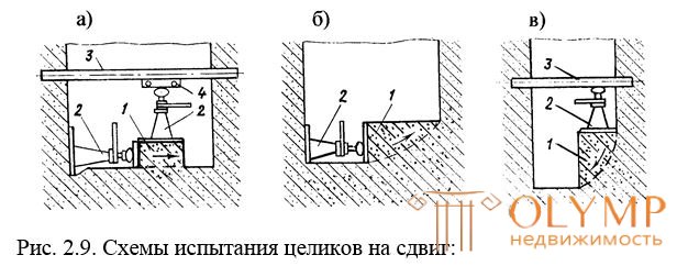
Fig. 2.9. Test schemes for shear pitch:
a - the destruction of the cylindrical pillar by shear in the cage;
b - bulging of the triangular pillar in the horizontal direction; in-collapse of the triangular pillar; 1 - pillar; 2 - jack;
3 - thrust beams; 4 - carriage to move the jack head
The results of observations during dynamic sensing are presented in the form of step plots, clearly showing how the resistance of the soil to the introduction of the probe is changing. If the sensing covers the entire area, then build profiles and maps.
The model differs from the dynamic one in that the immersion of the probe is carried out not by driving, but by pressing with the help of a hydraulic jack. The force developed by the jack is measured by a pressure gauge. The probe is also equipped with a sensor that allows at any time to determine the amount of soil resistance to the introduction of a cone.
With the help of static sounding it is possible to conduct the study of soft soils to a depth of 15-25 m at a speed of 0.5-1 m / min. The final material of static sensing is a graph that shows two curves: the soil resistance curve under the probe and the friction resistance curve.
Static sounding is used for:
- allocation of engineering geological elements;
- determination of the depth of the roof of the base layer;
- determination of soil resistance under the lower end and along the side surface of the piles;
- determination of soil characteristics;
And with the attempts and with with and and with and and with and to and and and and under r s -
to and m and. The test results of static loads are used to determine the bearing capacity of piles. The test pattern of the pile for vertical pressing load is shown in fig. 2.11. To test begin after the "rest" piles, the minimum duration of which is 3 days in sandy soils, and 6 days in powdered clay.
When testing a pile, a vertical indentation load is applied in steps equal to 1/10 of its intended maximum load. After application of the load step, the draft of the pile is recorded according to the indications of the prohibomers. Each step is maintained until conditional stabilization.
The test results are in the form of a graph of precipitation versus load. The resulting graph is used to determine the bearing capacity of the pile.
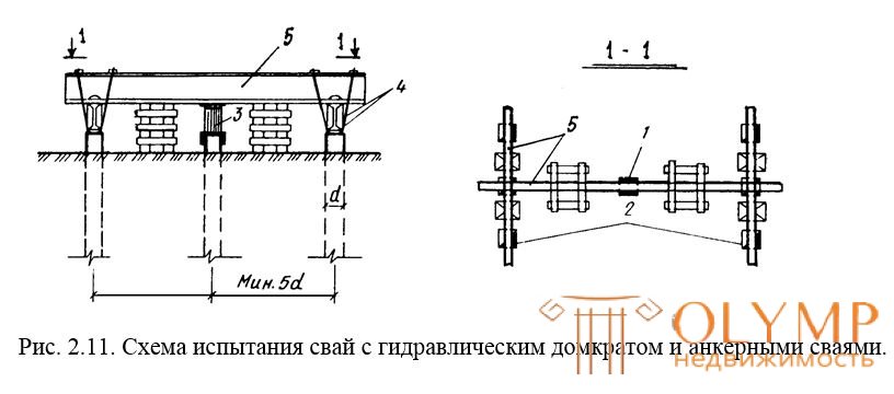
Fig. 2.11. Test setup for piles with hydraulic jack and anchor piles.
1 - test pile; 2 - anchor pile; 3 - jack; 4 - clamps,
5 - beams
Reliable values of ko effc and e nt a f and ltr a and u, especially for cohesive soils, can be obtained only in field conditions. Filtration properties of rocks in the field are determined by the following methods:
- pumping - if the filtration coefficient is determined below the groundwater level (OLA);
- loading and pumping of water into holes and wells - in non-saturated rocks;
- express method - for quick preliminary assessment of filtration indicators.
To determine the filtration coefficient, regime observations of the state of the hydrogeological situation can also be used, as a rule, under changing hydrogeological conditions and in the presence of a data bank of observations.
M e t o d o And h to and consists in pumping a certain amount of water from the central well. In this case, a decrease in the water level in the well is recorded. With the help of several observation wells, the shape of the depressed funnel formed around the main well is determined. The filtration coefficient is determined as a function of the water flow in the central well, taking into account the amount of reduction in the auxiliary wells in the auxiliary wells (Fig. 2.12).
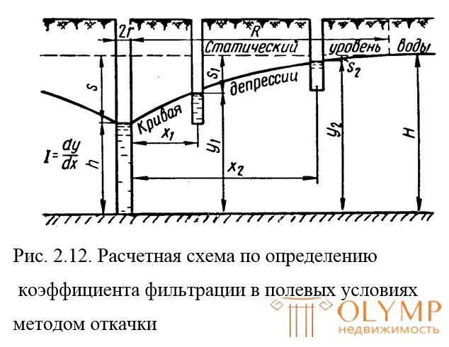
Fig. 2.12. Calculation scheme for determining the filtration coefficient in field conditions using the pumping method
M o d d a l and a will consist in injecting water into a non-saturated layer of rock and subsequent sampling of the rock to determine the moisture content with full water saturation directly under the water absorption pad. At the same time, water consumption and speed of movement of the front are wetted by the rock. Tests can be carried out in two ways:
- with a constant hydraulic head;
- at the established water flow.
E c s p re s s tem d is the instantaneous pouring of a certain volume of water with the subsequent measurement of the time of free fall of its level.
Что бы оставить комментарий войдите
Комментарии (0)