The calculation of the bent elements on the shear force
Calculation of the strength of bent elements by inclined sections.

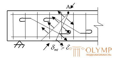
Experiments show that inclined cracks can occur near supports as a result of the joint action of a bending moment and shear force. From the course of resistance of materials it is known that the bending moment M causes normal stresses in the beam section  and shear force Q - shear stresses
  . On the inclined sections of the beam, the main tensile forces will act
  and main compressive stresses
  . When the main tensile stresses exceed the ultimate resistances of concrete to the stretching of Rbt, inclined cracks appear in it (stage Ia). Parts of the element located to the right and left of the inclined crack tend to rotate mutually around point A located in the compressed zone of the section above the crack. Such a turn is prevented by longitudinal reinforcement, crossed by a crack and working in tension, transverse reinforcement (clamps) and limb.
With a further increase in the load, the destruction of the element along an inclined section occurs (stage III).
Calculation of the effect of oblique compressive stresses.
When inclined cracks are formed, the concrete between them experiences the effect of main compressive stresses and simultaneously tensile forces from transverse reinforcement.
To ensure the strength of concrete in compression in the strip between inclined cracks, the following condition must be observed:
 ,(one)
Where  - coefficient taking into account the effect of transverse reinforcement
  where
where  ;
;
 - modulus of elasticity of concrete;
 - modulus of elasticity of reinforcing steel;
 ;
;
 where
where  - the cross-sectional area of a single yoke in the section of the beam; n is the number of clamps in the cross section of the element (the number of reinforcement bars obtained as a result of the calculation of the normal section)
 - the distance between the clamps.

 - for heavy concrete.
If condition (1) is not fulfilled, it is necessary to increase the dimensions of the section, or to increase the class of concrete.
Oblique crack in the cross section is not formed if  .
.
This condition corresponds to the approximate experimental dependence:
 , (2)
, (2)
Where  ;
;  - for heavy concrete.
Subject to condition (2), the calculation of the inclined sections of the transverse force is not required, and the reinforcement can be assigned for constructive reasons. If condition (2) is not fulfilled, then the strength of the section must be ensured by setting the shear reinforcement in accordance with the calculation (see the block diagram).
Design requirements
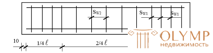
In accordance with the SNiP, the distance between the transverse rods in the elements, determined by structural considerations, take:
a) On the supporting areas equal to 1/4  (3)
(3)
for beams with h  450mm =>
  and not> 150mm
b) For beams with h> 450mm =>  and not> 500mm (4)
c) the rest of the span at any height h
 and not> 500mm (5)
The diameter of the transverse rods is taken from the table “Ratio of rods” from the condition of the welding technology.
Plot of materials.
In order to save metal, part of the longitudinal reinforcement may not be brought to the support and be discarded in the span where it is not required by calculation. In this case, rast. degrees must be got beyond the theoretical point of break (i.e. for section 1-1, in which these degrees are not required by calculation) for a length not <20d (where d is the diameter of the terminating rod).
Places theoretical breakage of rods set graph-analytical method. To this end, the plot of bending moments from an external load is applied on the same scale as a plot of moments perceived by the cross section of the element with actually existing stretched reinforcement. Let, for example, in a beam, the armature of 4 rods 1,2,3,4 is selected at the greatest moment
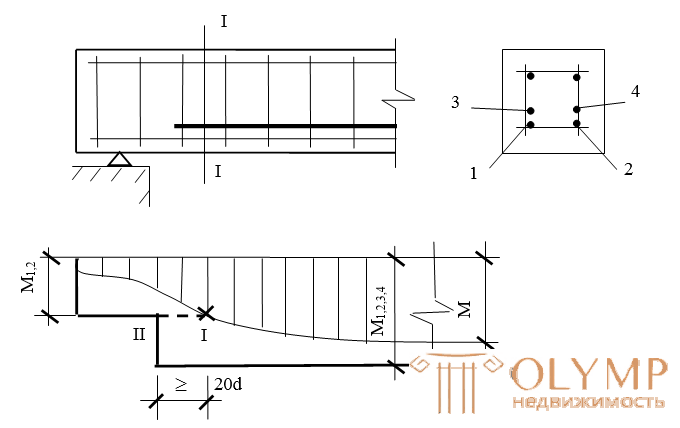
Two of them. 1 and 2 are brought to the support, and the rods 3 and 4 are cut off in the span. To determine the place of their theoretical cliff on the graph in the accepted scale, they postpone the moment perceived by the section reinforced with rods 1 and 2 with an area  and draw a horizontal line parallel to the axis. The place of intersection of this line with the curve of bending moments (Section 1-1) will be the place of the theoretical separation of 2 rods.
Example number 1
Given : Q = 25kN
b = 20cm
h = 45cm
a = 3cm
B20; γbi = 1
longitudinal reinforcement
2  20 AIII
Rb = 11.5 MPa
Rbt = 0.9 MPa
Rsw = 175 MPa
Q = 25kN
Es = 2.0  105mPa
Eb = 27 103mPa
Check the strength of the section
Decision:

Determined by design requirements
1) n = 2; dsw = 6 AI, since h = 45, => Sw =  =
= 
2) 

3) calculate 
4) calculate  check the condition
five) 
 tt.e. inclined cracks are not formed.
6) check the condition

Conclusion: inclined cracks are not formed and the strength of the inclined section on the effect of shear force is provided.
Example # 2
Given: Q = 100kN
Check condition 
100Н> 45.4кН - the condition is not met, go to the next step:
7) calculate 
8) calculate 
9) check the condition: 
Conclusion: the strength of the oblique section on the action of shear force is provided.
Example # 3
Shear force Q = 150kN
9) check the condition:

150> 110 => the condition is not met, therefore we reduce the spacing of the transverse rods Sw = 100mm
3) we calculate: 
four) 
5) Check: 
150 <363 => inclined cracks are not formed.
6) Clause 6 is not satisfied.
150> 45.4
7) Calculate: 
8) Calculate: 
9) Check the condition:  150> 124.7 - the condition is not met, it is necessary to increase the diameter of the transverse reinforcement to 8 mm and again make a check
Variants of tasks for the calculation of the transverse force.
option | b | h | a | B |
| Fittings | Q | the task
|
one | 20 | 40 | 3.0 | 15 | 1.0 | 3¯22IIA | 50 | Check the strength of the cross section Q≤Q |
2 | 21 | 41 | 3.1 | 20 | 0.85 | 218IIIA | 55 | |
3 | 22 | 42 | 3.2 | 25 | 0.9 | 2¯25AII | 65 | |
four | 23 | 43 | 3.4 | 20 | 1.0 | 3¯18АIII | 60 | |
five | 24 | 44 | 3.5 | 15 | 0.8 | 2¯22AII | 70 | |
6 | 25 | 45 | 3.6 | 12.5 | 0.9 | 3¯20АIII | 75 | |
7 | 20 | 46 | 3.7 | 15 | 0.85 | 2¯25AII | 80 | |
eight | 21 | 47 | 4.0 | 20 | 1.0 | 218AIII | 85 | |
9 | 22 | 48 | 3.3 | 25 | 0.9 | 3¯25АII | 65 | |
ten | 23 | 49 | 3.5 | thirty | 0.8 | 2¯20АIII | 58 | |
eleven | 24 | 50 | 3.2 | 12.5 | 0.95 | 3¯18AII | 70 | |
12 | 25 | 40 | 3.1 | 15 | 0.85 | 2¯22АIII | 65 | |
13 | 20 | 41 | 3.7 | 20 | 0.9 | 3¯20АII | 85 | |
14 | 21 | 42 | 3.5 | 25 | 1.0 | 218AIII | 70 | |
15 | 22 | 43 | 3.0 | thirty | 1.0 | 3¯25АII | 75 | |
sixteen | 23 | 44 | 3.4 | 15 | 0.85 | 2¯20АIII | 60 | |
17 | 24 | 45 | 3.8 | 12.5 | 0.9 | 3¯20АII | 87 | |
18 | 25 | 46 | 3.9 | 20 | 0.85 | 218AIII | 78 | |
nineteen | 20 | 40 | 3.8 | thirty | 1.0 | 2¯25AII | 59 | |
20 | 21 | 41 | 4.0 | 25 | 0.95 | 3¯18АIII | 65 | |
21 | 22 | 43 | 3.7 | 15 | 0.8 | 2¯20АII | 64 | |
22 | 23 | 44 | 3.8 | thirty | 1.0 | 3¯22АIII | 60 | |
23 | 24 | 42 | 3.1 | 20 | 0.8 | 218AII | 85 | |
24 | 25 | 50 | 3.4 | 15 | 0.95 | 3¯25АII | 75 | |
25 | 22 | 48 | 3.5 | 12.5 | 1.0 | 2¯20АIII | 70 |
 vi;
vi;
Что бы оставить комментарий войдите
Комментарии (0)