In the first period of the use of reinforced concrete, the overlapping of structures was carried out in the form of solid plates. However, such constructions are not rational, since the height of the compressed zone is 1/10 ... 1/15 of their height, and the stretched zone of the cross-section of concrete is not taken into account in the calculation of strength and serves to accommodate the reinforcement.

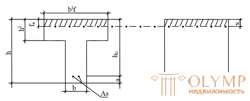
If part of the concrete is removed from the stretched zone, leaving it only near the reinforcing bars, then a ribbed plate will be obtained. The plate carrying capacity will not change, and the consumption of concrete and the weight of the structure will be significantly reduced. Such elements, called Tauri, are widely used in the form of beams, decking, as a part of monolithic ribbed floors.
Experience shows that in areas remote from the edge of the voltage will be less. This is taken into account by the conditional decrease in the width of the overhangs entered into the calculation.
1) b'f = b + 12h'f npu h'f  0, lh
0, lh
2) b'f = b + 6h'f at 0.05 h  h'f <0.1h
3) b'f = b with h'f <0.05h
When calculating T-shaped beams, two cases are distinguished: 1. A compressed section area is within a shelf, or below the shelf
CASE 1 (x h f ')
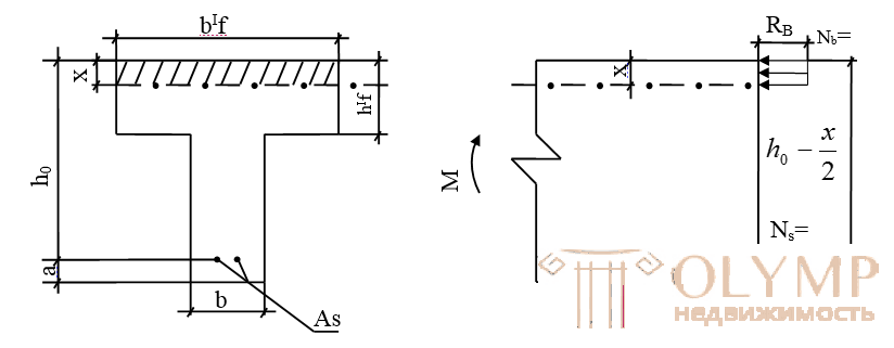
Case 1 occurs in sections with a developed shelf, when the external bending moment is less than or equal to the internal moment perceived by the compressed section shelf relative to the center of gravity of the reinforcement.
T-shaped section of this type is calculated as rectangular with dimensions b'f and h, since the area of the stretched concrete does not affect the bearing capacity. For the calculation, the formulas obtained for rectangular section with single reinforcement are used, in which "b" is replaced with "b'f".
l. Rb • b'f • x = Rs • As (1)
2. M Rb • b'f • x • (ho - x / 2)
3. M Rs • As • (ho - x / 2)
Selection of a T-section can be made, as for a rectangular section according to tabular data using the formulas:
4. A0 = M / Rb • b'f • ho2 Aomax.
5. As = M /  • ho • Rs
CASE 2 (x> h'f)
The neutral axis extends beyond the shelf and intersects the edge, (x> h'f), i.e. the external design moment will be greater than the internal moment perceived only by the compressed shelf. Tavrovye sections of this type are found in the calculation of beam structures with a small width of the overhangs of the shelf.
To obtain the calculated formulas, the bending moment perceived by the section is divided into two points:
but). Mfl - perceived by the shelf overhangs and the corresponding Asfl reinforcement.
b). Mrib - perceived by the compressed concrete edges and the corresponding reinforcement As.rib.
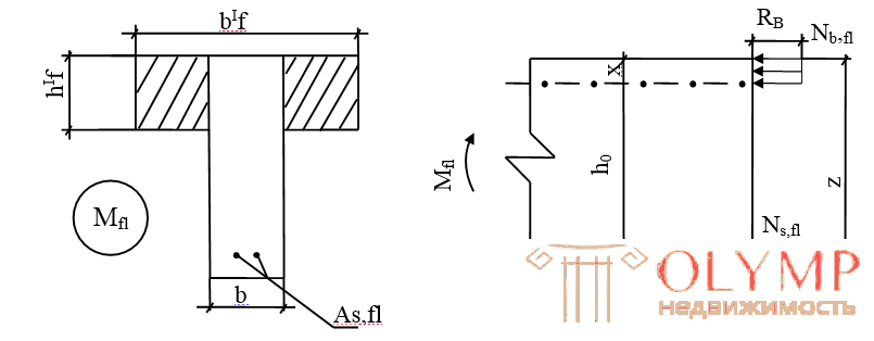
The concrete of the overhangs of the flange works for compression, and the tension is the corresponding part of the entire reinforcement As.rib. This section takes the moment:
6). Mfl = Nb, fl • z = Rb • (b'f-b) • h'f • (ho - h'f / 2) (6)
From the condition of equality "0" the sum of the projections of all forces on the element axis:
Nb, fl = Nsfl
Rb • (b'f-b) • h'f = Rs • As fl, from where
7). As fl = Rb • (b'f-b) • h'f / Rs (7)
This reinforcement constitutes only a part of the complete reinforcement As, now we will find the rest of the reinforcement corresponding to the reinforcement of the rib As.rib.
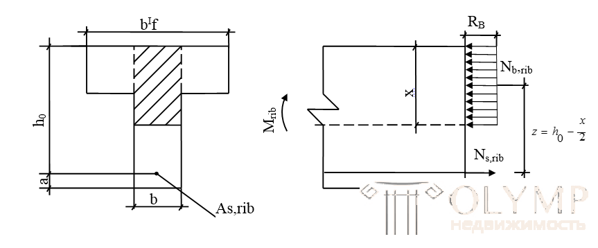
The rib concrete is working in compression at the height of the compressed zone x, and in tension the rest of the entire tensile reinforcement As.rib.
The stress state of this scheme is fully consistent with the stress state of a rectangular section with a height of "h" and a width of "b" with a single reinforcement, which perceives the moment:
eight). Mrib = M- Mfl (8)
The area of the As.rib reinforcement is defined as for a rectangular section with a single reinforcement width “b”:
9). A0 = Mrib / Rb • b • ho2 Aomax. (9)
10. As rib = Mrib / • ho • Rs (100)
The total cross section of tensile reinforcement is determined by the formula:
eleven). As = As fl + As.rib (11)
Further, according to table 7 of the application, we find the diameter and the number of longitudinal bars required for the reinforcement of the beam.
When calculating T-sections, determine which design case (x h f ') or (x> h'f) we have, can be as follows:
find the boundary moment MX = h'f = Rb • b'f • h'f • (ho - h'f / 2) (12)
If the current moment from external forces M Mh = h'f, then we have the 1st case, if M> Mx = h'f, we have the 2nd case.
When calculating T-sections, it is most often necessary to solve the problem of determining the cross-sectional area of As reinforcement for given section sizes, material classes and the calculated bending moment "M"
Decision plan.
1. Set the estimated width of the shelf b'f.
2. According to the formula (12), calculate Мh = h'f and determine which calculation case the section relates to;
3. Find the cross-sectional area of the armature As:
3.1 at (x h f ') - as for a rectangular section of width b'f according to formulas (4) and (5)
3.2 when (x> h'f) - first determine Mfl by the formula (6) and As fl
according to the formula (7). Then Mrib is determined by the formula (8) and As rib by the formula (10), as for a rectangular beam with the width "b". The total cross section of tensile reinforcement is found by the formula (11).
Type 2 Task
If you want to establish the carrying capacity of a given section of the formula (1) determine the height of the compressed zone:
X = Rs • As / Rb • b'f
If (x hf '), my moment perceived by the section, is determined
according to formula 2:
M Rb • b'f • x • (ho - x / 2)
If x> h'f, then the calculation procedure is as follows:
1. Determine As, fl no by the formula (7) and Mfl by the formula 6.
2. Find As, rib from formula 11
3. Count Mrib, as for a rectangular section with
single valve:
first determine:
x = Rs • As, rib / Rb • b, and then:
4. Mrib = Rs • As, rib (ho - x / 2)
5. Determine the total moment perceived by the section (its carrying capacity):
M = Mfl + Mrib
EXAMPLE N1
Determine the area of As reinforcement in the element of the T-section according to the following data:
M = 42 kNm;
Armature class A111
Concrete B15;
b'f = 80cm; Yi = 1
h = 40 cm; h'f = 4 cm;
b = 14 cm
a = 3cm
Decision.
According to the tables of the application, we determine the calculated characteristics:
Rb = 8.5 • 1 = 8.5mPa; Rs = 365mPa
To determine the estimated width of the flange, we find the ratio h'f / h = 4/40 = 0.1– taken b'f = b + 12h'f = 14 + 12 • 4 = 62cm
1). Find the useful (working) section height ho = h-a = 40-3 = 37cm
2). We calculate the boundary moment Мх = h'f = Rb • b'f • h'f • (ho - h'f / 2) (100) =
8.5 • 62 • 4 • (37-4 / 2) • (100) = 7378000nsm = 73.8kNm> 42 kNm, therefore, we have the 1st calculation case.
We define As as for a rectangular section of width b'f
3) .A0 = M / Rb • b'f • ho2 Aomax
A0 = 42 • 105 / 8.5 • 62 • 372 • (100) = 0.058 <Aomax = 0.42 (tab.5 of the appendix)
By A0 we define = 0.976 (tab.6 of the application)
4). Find As = M / • ho • Rs (100) = 42 • 105 / 0.976 • 37 • 365 (100) = 3.26 cm2
According to table 7 of the application we take 3¯12АIII with As, fact = 3.39 cm2
EXAMPLE N2
According to the previous example, determine As if M = 86 kNm.
Decision.
Set the settlement case:
Since M> MX = h'f (86> 73.8), we have 2 cases (x> h'f)
1). Determine:
Mfl = Rb • (b'f-b) • h'f • (ho-h'f / 2) = 8.5 • (62-14) • 4 • (37-4 / 2) (100) = 5712000Nsm = 57.1kNm
2). We determine As fl = Rb • (b'f-b) • h'f / Rs = 57.1 • 105/365 • (37-4 / 2) (100) = 4.46 cm2
3). We calculate Mrib = M- Mfl = 86-57.1 = 29 kNm
4). We calculate A0 = Mrib / Rb • b • ho2 Aomax
A0 = 29 • 105 / 8.5 • 14 • 372 (100) = 0.172 <Aomax; = 0.9
5) .As rib = Mrib / • ho • Rs (100) = 29 • 105 / 0.9 • 37 • 365 (100) = 2.39 cm2
6). We calculate As = As fl + As.rib = 4.46 + 2.39 = 6.85 cm2
According to table 7 of the application we take 4¯16АIII with As, fact = 8.04 cm2
T-section reinforcement
Given: 2¯ 22 ASH L = 7.8m
Product brand | Item Position | Name | Qty | Mass 1det. (kg.) | Product weight |
CR2 | one | ¯10АIII L = 1940 | four | 1.2 | 5.88 |
2 | ¯3ВР1 L = 980 | 20 | 0.054 |
Product brand | Item Position | Name | Qty | Mass 1det. (kg.) | Product weight | |||||
KP1 | one | 0 22 AIII / = 7780 | one | 23.2 | 34.15 | |||||
2 | 0 10A1 / = 7780 | one | 4.8 | |||||||
3 | 08A1 / = 38O | 41 | 0.15 | |||||||
Position | Designation | Name | Count | Note | ||||||
Assembly units | ||||||||||
one | KPSK 2902 C-32 OSI KR-1 | skeleton flat KR-1 | 2 | |||||||
2 | KR-2 | skeleton flat KR-2 | 2 | |||||||
Details | ||||||||||
3 | 0UA1 / = 18O | 25 | 0.111 | |||||||
Materials | ||||||||||
four | Concrete B20 | m3 | 1.17 | |||||||
Steel consumption statement
Brand of elements. | Reinforcement products | Total | |||||||
Armature class | Armature class | Armature class | 82,84 | ||||||
B1 | AIII | AI | BP1 | ||||||
GOST 5781-82 | GOST 5781-82 | GOST 5781-82 | |||||||
022 | 010 | Total | 010 | 08 | Total | 03 | Total | ||
46.4 | 9.6 | 56 | 12.38 | 12.3 | 24.68 | 2.16 | 2.16 | ||
Questions for self-monitoring on the topic :
"The calculation of the bent elements of the T-section"
1. What is the advantage of T-shaped sections over rectangular?
2. How many cases are there for calculating T-sections?
3. How to determine the case of calculating the T-section?
4. What is the boundary moment?
5. What is the difference between reinforcing a T-section and a rectangular section?
6. What are the KR-2 frameworks for in beams of T-section?
7. How to determine the diameter and spacing of transverse reinforcement in the frame of the beam?
8. Name the types of reinforcement according to the nature of work in the frame of the beam.
Table 1
Design concrete resistance for limiting states of the first group of Rb and Rbt MPa depending on the class of concrete in compressive strength
Kind of resistance | Concrete | Concrete compressive strength class | ||||||||||||||||||||||||||||
B12.5 | B15 | IN 20 | B 25 | VZO | B 35 | B40 | ||||||||||||||||||||||||
Compression oseeoe (prismatic strength) Rb | Heavy had a grained | 7.5 | 8.5 | 11.5 | 14.5 | 17 | 19.5 | 22 | ||||||||||||||||||||||
Axial stretch Rbt | Heavy | 0.6 | 0.75 | 0.9 | 1.05 | 1.2 | 1.3 | 1.4 | ||||||||||||||||||||||
table 2 | ||||||||||||||||||||||||||||||
Calculated resistance fittings for group I of limit states Rs, MPa | ||||||||||||||||||||||||||||||
Stretched | Compressed rsc | |||||||||||||||||||||||||||||
Type and grade of steel; | longitudinal, transverse (clamps and limb) for bending on an inclined section. Rs | transverse (clamps and bends) in the calculation of the transverse force Rsw | ||||||||||||||||||||||||||||
Hot rolled round grade A- I | 225 | 175 | 225 | : ' | ||||||||||||||||||||||||||
Hot rolled periodic | ||||||||||||||||||||||||||||||
class profile: A-ll | 280 | 225 | 280 | |||||||||||||||||||||||||||
A-III d-8 mm | 355 | 285 | 355 | |||||||||||||||||||||||||||
A-III d- 10. ..40 mm | | 365 | 290 | 365 | |||||||||||||||||||||||||||
Wire reinforcing periodic profile class bp-i | . | |||||||||||||||||||||||||||||
d, mm: | ||||||||||||||||||||||||||||||
3 | 375 | 270 | 375 | |||||||||||||||||||||||||||
four | 370 | 265 | 365 | |||||||||||||||||||||||||||
five | 360 | 260 | 360 | |||||||||||||||||||||||||||
table 3 The ratio between the diameters of the welded rods | ||||||||||||||||||||||||||||||
The diameters of the rods in one direction d1 (mm) | 3 | four | five | 6 | eight | ten | 12 | 14 | sixteen | 18 | 20 | 22 | 25 | 28 | 32 | 36 | 40 | |||||||||||||
The smallest allowable diameters of rods in a different direction d2 (mm) | 3 | 3 | 3 | 3 | 3 | 3 | four | five | five | 6 | 6 | eight | eight | ten | ten | 12 | 12 | |||||||||||||
table 4
The modulus of elasticity of reinforcing steel Es
Type and grade of steel | The modulus of elasticity of reinforcement Es.MPa |
Core steel AI and A-II | 210,000 |
A-IIIb | 200,000 |
A-IV, A-VI, AT-IIIC | 190,000 |
Reinforcing Wire B-II, BP-II, BP-I | 200,000 170,000 |
Reinforcement ropes K-7, K-19 | 180,000 |
table 5
Table: Values  iAoMAh
Reinforcement class | Coefficient | ||||||
IN 20 | VZO | B40 | B50 | B60 | |||
AI |
| 0.65 | 0.59 | 0.55 | - | - | |
AOmax | 0.48 | 0.42 | 0.4 | - | - | ||
AP |
| 0.62 | 0.57 | 0.52 | 0.47 | 0.44 | |
AOmax | 0.43 | 0.41 | 0.38 | 0.36 | 0.34 | ||
A-III with ¯ 6-8 mm |
| 0.59 | 0.54 | 0.5 | 0.44 | 0.41 | |
AOmax | 0.42 | 0.39 | 0.37 | 0.34 | 0.33 | ||
table 6
Coefficient values AO,
|
| AO |
|
| AO |
0.41 | 0.795 | 0.326 | 0.57 | 0.715 | 0.408 |
0.42 | 0.79 | 0.332 | 0.58 | 0.71 | 0.412 |
- | - | - | 0.59 | 0.705 | 0.416 |
0.43 | 0.785 | 0.337 | 0.6 | 0.7 | 0.42 |
0.44 | 0.78 | 0.343 | |||
0.45 | 0.775 | 0.349 | 0.61 | 0.695 | 0.424 |
0.46 | 0.77 | 0.354 | 0.62 | 0,69 | 0.428 |
0.47 | 0.765 | 0.359 | 0.63 | 0.685 | 0.432 |
0.48 | 0.76 | 0.365 | 0.64 | 0.68 | 0.435 |
0.65 | 0.675 | 0.439 | |||
0.49 | 0.755 | 0.37 | 0.66 | 0.672 | 0.442 |
0.5 | 0.75 | 0.375 | |||
0.51 | 0.745 | 0.38 | 0.67 | 0.665 | 0.446 |
0.52 | 0.74 | 0.385 | 0.68 | 0.66 | 0.449 |
0.53 | 0.735 | 0.39 | 0,69 | 0.655 | 0.452 |
0.54 | 0.73 | 0.394 | 0.7 | 0.65 | 0.455 |
0.55 | 0.725 | 0.399 | _ | - | - |
0.56 | 0.72 | 0.403 | - | - | - |
0.01 | 0.995 | 0.01 | 0.21 | 0.895 | 0.188 |
0.02 | 0.99 | 0.02 | 0.22 | 0.89 | 0.196 |
0.03 | 0.985 | 0.03 | 0.23 | 0.885 | 0.203 |
0.04 | 0.98 | 0.039 | 0.24 | 0.88 | 0.211 |
0.05 | 0.975 | 0.048 | |||
0.06 | 0.97 | 0.058 | 0.25 | 0.875 | 0.219 |
0.26 | 0.87 | 0,226 | |||
0.07 | 0.965 | 0.067 | 0.27 | 0.865 | 0.236 |
0.08 | 0.96 | 0.077 | 0.28 | 0.86 | 0.241 |
0.09 | 0.955 | 0.085 | 0.29 | 0.855 | 0.248 |
0.1 | 0.95 | 0.095 | 0.3 | 0.85 | 0.255 |
0.11 | 0.945 | 0,104 | - | - | - |
0.12 | 0.94 | 0.113 | 0.31 | 0.845 | 0,262 |
0.32 | 0.84 | 0.269 | |||
0.13 | 0.935 | 0.121 | 0.33 | 0.835 | 0.275 |
0.14 | 0.93 | 0.13 | 0.34 | 0.83 | 0.282 |
0.15 | 0.925 | 0.13 | 0.35 | 0.825 | 0,289 |
0.16 | 0.92 | 0.147 | 0.36 | 0.82 | 0,295 |
0.17 | 0.915 | 0.155 | - | - | - |
0.18 | 0.91 | 0.164 | 0.37 | 0.815 | 0.301 |
0.19 | 0.905 | 0.172 | 0.39 | 0.805 | 0.314 |
0.2 | 0.9 | 0.18 | 0.4 | 0.8 | 0.32 |
table 7
Cross-sectional areas and mass of reinforcement bars
d | cross-sectional area (cm.kv.) when the number of rods | mass1 m | d | ||||||||
mm | one | 2 | 3 | four | five | 6 | 7 | eight | 9 | kg | mm |
3 | 0.071 | 0.14 | 0.21 | 0.28 | 0.35 | 0.42 | 0.49 | 0.57 | 0.64 | 0.055 | 3 |
four | 0.126 | 0.25 | 0.38 | 0.50 | 0.63 | 0.76 | 0.88 | 1.01 | 1.13 | 0.098 | four |
five | 0.196 | 0.39 | 0.59 | 0.79 | 0.98 | 1.18 | 1.37 | 1.57 | 1.77 | 0.154 | five |
6 | 0.283 | 0.57 | 0.85 | 1.13 | 1.42 | 1.70 | 1.98 | 2.26 | 2.55 | 0.222 | 6 |
7 | 0.385 | 0.77 | 1.15 | 1.54 | 1.92 | 2.31 | 2.69 | 3.08 | 3.46 | 0.302 | 7 |
eight | 0.503 | 1.01 | 1.51 | 2.01 | 2.51 | 3.02 | 3.52 | 4.02 | 4.53 | 0.395 | eight |
9 | 0.636 | 1.27 | 1.91 | 2.54 | 3.18 | 3.82 | 4.45 | 5.09 | 5.72 | 0.499 | 9 |
ten | 0.785 | 1.57 | 2.36 | 3.14 | 3.93 | 4.71 | 5.50 | 6.28 | 7.07 | 0.617 | ten |
12 | 1,510 | 2.26 | 3.39 | 4.52 | 5.65 | 6.79 | 7.92 | 9.05 | 10.18 | 0.888 | 12 |
14 | 1.539 | 3.08 | 4.62 | 6.16 | 7,69 | 9.23 | 10.77 | 12.31 | 13.85 | 1,208 | 14 |
sixteen | 2,011 | 4.02 | 6.03 | 8.04 | 10.05 | 12.06 | 14.07 | 16.08 | 18.10 | 1.578 | sixteen |
18 | 2.545 | 5.09 | 7.63 | 10.18 | 12.72 | 15.27 | 17.81 | 20.36 | 22.90 | 1,993 | 18 |
20 | 3.142 | 6.28 | 9.41 | 12.56 | 15.71 | 18.85 | 21.99 | 25.14 | 28.28 | 2.466 | 20 |
22 | 3,801 | 7.60 | 11.40 | 15.20 | 19.00 | 22.81 | 26.61 | 30.41 | 34.21 | 2,994 | 22 |
25 | 4,909 | 9.82 | 14.73 | 19.63 | 24.54 | 29.45 | 34.36 | 39.27 | 44.18 | 3,853 | 25 |
28 | 6.158 | 12.32 | 18.47 | 24.63 | 30.79 | 36.95 | 43.10 | 49.26 | 55.42 | 4.83 | 28 |
32 | 8,043 | 16.08 | 24.13 | 32.17 | 40.21 | 48.25 | 56.30 | 64.34 | 72.38 | 6.313 | 32 |
36 | 10.18 | 20.36 | 30,54 | 40.72 | 50.9 | 61.08 | 71.26 | 81.44 | 91.62 | 7.99 | 36 |
40 | 12.56 | 25.12 | 37.68 | 50.24 | 62,8 | 75.36 | 87.92 | 100.48 | 113.04 | 9.87 | 40 |
CALCULATION OF TARPSETS (TYPE 2) A s =?
No. Var | M (kNm) | in (cm) | ′ f | h′f | concrete | armature | Twi | a (cm) | h (cm) | l (m) | |
one | 120 | nineteen | 60 | ten | B15 | AII | 0.8 | 3.0 | 40 | 6.0 | |
2 | 123 | 18 | 61 | eleven | IN 20 | AIII | 0.85 | 3.2 | 41 | 6.5 | |
3 | 136 | 17 | 62 | 12 | B25 | AII | 0.9 | 3.3 | 42 | 6.6 | |
four | 130 | 22 | 63 | 14 | B30 | AIII | 0.85 | 3.4 | 43 | 6.7 | |
five | 124 | 24 | 64 | 15 | B15 | AII | 0.9 | 3.5 | 44 | 6.8 | |
6 | 132 | 25 | 65 | ten | IN 20 | AIII | 0.8 | 3.6 | 45 | 6.9 | |
7 | 118 | 26 | 66 | eleven | B25 | AII | 0.85 | 3.7 | 46 | 7.0 | |
eight | 129 | 20 | 67 | 12 | B30 | AIII | 0.9 | 3.8 | 47 | 7.1 | |
9 | 137 | 27 | 68 | 13 | B15 | AII | 0.8 | 3.9 | 48 | 7.2 | |
ten | 119 | 28 | 69 | 14 | IN 20 | AIII | 0.85 | 4.0 | 49 | 7.3 | |
eleven | 121 | 29 | 70 | 15 | B25 | AII | 0.9 | 3.0 | 50 | 7.4 | |
12 | 127 | thirty | 71 | ten | B30 | AIII | 0.8 | 3.2 | 40 | 7.5 | |
13 | 135 | 15 | 72 | eleven | B15 | AII | 0.85 | 3.3 | 41 | 7.6 | |
14 | 140 | sixteen | 73 | 12 | IN 20 | AIII | 0.9 | 3.4 | 42 | 7.7 | |
15 | 141 | 17 | 60 | 13 | B25 | AII | 0.8 | 3.5 | 43 | 7.8 | |
sixteen | 142 | 18 | 61 | 14 | B30 | AIII | 1.0 | 3.6 | 44 | 7.9 | |
17 | 143 | nineteen | 62 | 15 | B15 | AII | 1.0 | 3.7 | 45 | 8.0 | |
18 | 144 | 20 | 63 | ten | IN 20 | AIII | 1.0 | 3.8 | 46 | 8.1 | |
nineteen | 145 | 21 | 64 | eleven | B25 | AII | 1.0 | 3.9 | 47 | 8.2 | |
20 | 149 | 22 | 65 | 12 | B30 | AIII | 1.0 | 4.0 | 48 | 8.3 | |
21 | 125 | 23 | 66 | 13 | B15 | AII | 1.0 | 3.0 | 49 | 8.4 | |
22 | 126 | 24 | 67 | 14 | B25 | AIII | 1.0 | 3.2 | 50 | 8.5 | |
23 | 129 | 25 | 68 | 15 | B30 | AII | 1.0 | 3.3 | 51 | 8.6 | |
24 | 138 | 26 | 69 | 12 | B15 | AIII | 1.0 | 3.4 | 40 | 8.7 | |
25 | 140 | 27 | 70 | 14 | IN 20 | AII | 1.0 | 3.5 | 52 | 8.8 |
CALCULATION OF TARED SECTIONS. Check M <Msech
No. Var | M (kNm) | in (cm) | ′ f | h′f | concrete | armature | Twi | a (cm) | h (cm) | l (m) | As |
one | 120 | nineteen | 60 | ten | B15 | AII | 0.8 | 3.0 | 40 | 6.0 | 14.3 |
2 | 123 | 18 | 61 | eleven | IN 20 | AIII | 0.85 | 3.2 | 41 | 6.5 | 11.5 |
3 | 136 | 17 | 62 | 12 | B25 | AII | 0.9 | 3.3 | 42 | 6.6 | 13.1 |
four | 130 | 22 | 63 | 14 | B30 | AIII | 0.85 | 3.4 | 43 | 6.7 | 15.4 |
five | 124 | 24 | 64 | 15 | B15 | AII | 0.9 | 3.5 | 44 | 6.8 | 15.2 |
6 | 132 | 25 | 65 | ten | IN 20 | AIII | 0.8 | 3.6 | 45 | 6.9 | 12.9 |
7 | 118 | 26 | 66 | eleven | B25 | AII | 0.85 | 3.7 | 46 | 7.0 | 11.6 |
eight | 129 | 20 | 67 | 12 | B30 | AIII | 0.9 | 3.8 | 47 | 7.1 | 16,1 |
9 | 137 | 27 | 68 | 13 | B15 | AII | 0.8 | 3.9 | 48 | 7.2 | 15.3 |
ten | 119 | 28 | 69 | 14 | IN 20 | AIII | 0.85 | 4.0 | 49 | 7.3 | 17.2 |
eleven | 121 | 29 | 70 | 15 | B25 | AII | 0.9 | 3.0 | 50 | 7.4 | 14.6 |
12 | 127 | thirty | 71 | ten | B30 | AIII | 0.8 | 3.2 | 40 | 7.5 | 15.3 |
13 | 135 | 15 | 72 | eleven | B15 | AII | 0.85 | 3.3 | 41 | 7.6 | 16,1 |
14 | 140 | sixteen | 73 | 12 | IN 20 | AIII | 0.9 | 3.4 | 42 | 7.7 | 12.8 |
15 | 141 | 17 | 60 | 13 | B25 | AII | 0.8 | 3.5 | 43 | 7.8 | 13.0 |
sixteen | 142 | 18 | 61 | 14 | B30 | AIII | 1.0 | 3.6 | 44 | 7.9 | 17.0 |
17 | 143 | nineteen | 62 | 15 | B15 | AII | 1.0 | 3.7 | 45 | 8.0 | 10.9 |
18 | 144 | 20 | 63 | ten | IN 20 | AIII | 1.0 | 3.8 | 46 | 8.1 | 15.1 |
nineteen | 145 | 21 | 64 | eleven | B25 | AII | 1.0 | 3.9 | 47 | 8.2 | 16.3 |
20 | 149 | 22 | 65 | 12 | B30 | AIII | 1.0 | 4.0 | 48 | 8.3 | 14.6 |
21 | 125 | 23 | 66 | 13 | B15 | AII | 1.0 | 3.0 | 49 | 8.4 | 15.7 |
22 | 126 | 24 | 67 | 14 | B25 | AIII | 1.0 | 3.2 | 50 | 8.5 | 18.2 |
23 | 129 | 25 | 68 | 15 | B30 | AII | 1.0 | 3.3 | 51 | 8.6 | 18.6 |
24 | 138 | 26 | 69 | 12 | B15 | AIII | 1.0 | 3.4 | 40 | 8.7 | 11.3 |
25 | 140 | 27 | 70 | 14 | IN 20 | AII | 1.0 | 3.5 | 52 | 8.8 | 15.0 |
Что бы оставить комментарий войдите
Комментарии (0)